
Frameless and torque motors
Rotor and stator kits built directly into the machine, removing couplings and gearing from the axis. Tell us the application and we'll specify the right product, and the parts around it, for your machine.
Engineering support · Product sourcing · Procurement
Get help selecting and sourcing frameless and torque motors
Send your part number or describe the application. We’ll review the requirement and help with product selection, sourcing, pricing and lead times.
- Exact parts and engineer-checked alternatives
- Manufacturer-direct options where available
- Standard, modified and custom solutions
No obligation to buy. Have a datasheet, drawing or nameplate photo? Reply to your confirmation email to attach it.
Need help choosing? Build a specification →Need help choosing? Open the specification builder
Spec builder
Specify frameless and torque motors
Select every part you need, answer the questions an applications engineer would ask, and see your summary before we ask for any details.
- 1Products
- 2Performance
- 3Environment
- 4Volumes
- 5Your spec
In short:A frameless motor is a rotor and stator supplied without housing, shaft or bearings, so you build it straight into your machine's structure. Choose one when axial length, weight, stiffness or a large through-bore matter more than drop-in convenience, and size it on the thermal conditions it will really see once installed.
What frameless and torque motors are
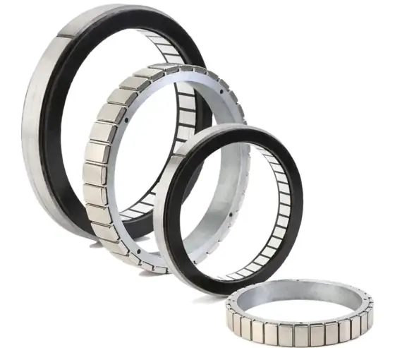
A frameless motor is a brushless motor without the parts that make it a stand-alone product. You get a wound stator and a magnet rotor. The housing, shaft, bearings, feedback and cooling are yours. The stator is bonded or clamped into a bore in your structure, and the rotor goes onto the shaft you are driving.
That is the point of them. Removing the motor’s own housing, bearings and coupling shortens the axis, saves mass and puts the torque directly where it is needed. Kollmorgen notes that a direct-drive axis has no mechanical compliance, backlash or lost motion between motor and load (Kollmorgen). Large-diameter kits usually leave a big through-bore for cables, slip rings, optics or a coaxial brake.
Typical uses are robot and cobot joints, gimbals and stabilised platforms, rotary and index tables, medical devices, semiconductor stages and spindle-like axes. Bus voltages run from 48 VDC or less up to around 680 VDC, and continuous torque from fractions of a newton metre to several thousand.
Types compared
| Type | What you get | Best for | Trade-offs |
|---|---|---|---|
| Frameless kit (slotted) | Rotor and stator only | Robot joints, compact axes, highest torque per mass | You design bearings, housing, cooling and feedback |
| Frameless kit (slotless/ironless) | Rotor and stator, no cogging | Gimbals, optics, metrology, very smooth low speed | Lower torque density |
| Housed direct-drive (torque) motor | Complete motor with bearings and encoder | Rotary tables and indexers without gearing | Larger and heavier than a kit |
| Linear motor (iron-core or ironless) | Forcer and magnet track | Direct-drive linear stages, gantries | Open magnet track, needs linear encoder and guides |
| Gear-integrated actuator | Motor, strain-wave gear and encoder in one unit | Joints and positioners where integration time matters | Gear compliance and lost motion return |
Frameless kits
Kits are offered by diameter and stack length, in several windings for different bus voltages. Akribis ADR-F covers small 48 VDC kits for compact joints; Akribis ADR-P covers larger high-voltage kits with big through-bores.
Housed direct-drive motors
Housed torque motors bring their own bearing and encoder and bolt straight to a table or fixture. Examples include Akribis AXD, the absolute-encoder AXD-ERA, and the ironless, zero-cogging ACD for very smooth low-speed motion.
Linear motors, briefly
The linear equivalent is a forcer moving over a magnet track. Iron-core types such as Akribis AKM give high force; ironless U-channel types such as Akribis AUM remove cogging for smooth scanning. Tubular motors such as LinMot P10-54 package the magnets inside a sealed rod.
Gear-integrated actuators
Where a joint needs a ratio, motor and strain-wave gear can be bought as one unit, for example the hollow-shaft Harmonic Drive FHA-C. This saves integration time at the cost of design freedom.
Frameless vs housed vs geared: when to use which
- Frameless kit when axial length, mass and through-bore drive the design, and you have the mechanical and thermal engineering capacity to integrate it.
- Housed direct drive when you want gearless stiffness and accuracy on a table or indexer without designing bearings and encoder mounts.
- Frameless plus strain-wave gear for most robot joints, where torque per kilogram matters and a small amount of gear compliance is acceptable. A 100:1 gear reduces reflected load inertia by 10,000 times.
- Housed servo plus gearbox when cost and lead time beat integration. See servo and stepper motors and gearboxes.
How to size a frameless motor
1. Torque and speed at the joint
Work out the peak and RMS torque from the move profile, payload, arm or table inertia and gravity. If the joint is geared, divide by the ratio and efficiency to get motor torque, and multiply speed by the ratio.
2. Use the motor constant
The motor constant Km = Kt / √R (Nm/√W) tells you how much torque you get per watt of heat. Allient notes that Km rises faster with diameter than with length, so the largest diameter and shortest stack that meets the Km target is usually the most efficient choice (Allient). Copper loss at a given torque is (T / Km)². Datasheets do not always quote Km; you can calculate it from Kt and resistance.
3. Model the thermal path
This is the step that catches most designs out. Kollmorgen’s TBM ratings, for instance, assume 25 °C ambient and a specified heat sink, with hot parameters quoted at a 155 °C winding temperature (Kollmorgen TBM guide). Your housing may be smaller, enclosed or near other heat sources. Kollmorgen recommends steel or aluminium housings with at least 4–6 mm wall thickness and warns that stainless steel conducts heat poorly. Allient adds that a power-off brake adds heat while the joint is moving. Build a thermal model per joint and expect to derate.
Also consider what the heat reaches. A winding running near its limit can damage bearing grease, gear lubricant and encoder electronics nearby.
4. Choose feedback and temperature sensing
Absolute encoders give commutation and position at power-up, removing separate Hall sensors; Kollmorgen suggests 18-bit or higher for high-repeatability axes, with resolvers (typically 12–16 bits) for high shock. In geared joints, Allient and TQ both describe a second encoder on the output to measure true joint position. For temperature, a linear sensor such as a PT1000 helps characterise the motor during prototyping; a PTC gives a simple trip.
5. Cogging and smoothness
Slotted designs give the most torque but have some cogging. Kollmorgen’s TBM data quotes peak-to-peak cogging per model, from about 0.01 Nm on small frames to around 0.3 Nm on the largest. For gimbals and scanning optics, choose slotless or ironless designs, or ask for cogging data and compensation options. Allient notes that higher-frequency cogging is generally easier to tune out than low-frequency cogging.
Integration and common mistakes
- Trusting datasheet continuous torque. It is only valid for the test heat sink and ambient.
- Stainless or thin housings. These trap heat; increase wall section or use aluminium.
- Poor concentricity. Follow the manufacturer’s tolerances for rotor and stator alignment; an uneven air gap causes torque ripple and unbalanced magnetic pull.
- Unsafe assembly. Rotor magnets pull hard on the stator and on steel tools. Plan fixtures for insertion.
- Bearings sized for the motor, not the load. The machine’s bearings carry everything, and should be serviceable if radial loads are high.
- No brake plan. Fit the brake on the primary driven shaft and include its heat in the budget.
- Encoder mounted on a compliant path. Mount it rigidly to the rotor or output it measures.
For robot joints in particular, the frameless motor sizing guide for robot joints works through a full example, and robotics and cobots covers the wider system.
What to send an engineer for a quote
- Peak and RMS torque, maximum speed, and the move profile
- Available envelope: maximum OD, minimum ID (through-bore), axial length
- Bus voltage and drive current limits
- Housing material, wall section, ambient temperature and any cooling
- Feedback type and resolution, and whether you need an output-side encoder
- Gear ratio and type if geared
- Brake, smoothness or cogging limits, and any vacuum, cleanroom or radiation requirements
- Expected volumes, since custom windings and stack lengths are often possible
Send these through the spec builder below and our specialist engineering and supply partners will shortlist kits or housed units to suit.
Guides
Where frameless and torque motors are used
What we need to know to specify frameless and torque motors
These are the questions an applications engineer works through first. Approximate answers are fine: ranges narrow the options quickly, and we confirm the details with you.
- Outer diameter: Under 50 mm, 50–100 mm, 100–200 mm, Over 200 mm
- Peak torque: Under 2 Nm, 2–20 Nm, 20–200 Nm, Over 200 Nm
- Use: Robot joint, Gimbal / pan-tilt, Rotary table, Spindle
- Hollow shaft: Yes, No
We also ask about the environment (washdown, outdoor, subsea, ATEX, vacuum, shock and EMC), annual quantities and timescale, because these decide whether a standard, modified or custom design is the best fit.
39 series compared
Series from 18 manufacturers, grouped by type. Figures are the highest published for each series. Open a series for the full specification and, for brands outside our supply network, the alternatives that meet or exceed it.
Frameless torque motor (25)
| Brand | Series | Continuous torque | Peak torque | Speed |
|---|---|---|---|---|
| Akribis Systems | ADR-F | 3.75 Nm | 11.22 Nm | 3,000 rpm |
| Akribis Systems | ADR-P | 365 Nm | 985.5 Nm | — |
| Motion Control Products | TI Series In-Runner Frameless Direct Drive Torque Motors | 70 Nm | — | — |
| WITTENSTEIN alpha | cyber torque motor | — | 1,700 Nm | — |
| Kollmorgen | KBM / KBMS | 54.6 Nm | 218 Nm | — |
| Kollmorgen | TBM2G | 6.03 Nm | — | — |
| maxon | EC frameless DT / HT | 2.84 Nm | — | — |
| CubeMars | RI Series | — | 4.95 Nm | — |
| CubeMars | RO Series | — | 12 Nm | — |
| HIWIN | TM-2 / IM-2 torque motors | 3,375 Nm | 6,000 Nm | 5,450 rpm |
| Allient | MegaFlux frameless torque motors | 181 Nm | — | — |
| Allient | KinetiMax HPD frameless motors | — | — | — |
| Allient | HT frameless torque motors | 9.2 Nm | — | 14,500 rpm |
| Schaeffler | RKI torque motors (IDAM) | 11,864 Nm | 17,670 Nm | 3,000 rpm |
| Schaeffler | RIB torque motors (IDAM) | — | 40,000 Nm | — |
| ETEL | TMB+ | 22,300 Nm | 42,900 Nm | 4,590 rpm |
| ETEL | TMKi | 11,600 Nm | 20,600 Nm | 5,200 rpm |
| ETEL | TMM | 1,170 Nm | 4,990 Nm | 4,400 rpm |
| Tecnotion | QTL torque motors | 907 Nm | 1,789 Nm | — |
| Tecnotion | QTR torque motors | 103.9 Nm | 155.3 Nm | — |
| TQ-RoboDrive | ILM Servo-Kits | 3.9 Nm | 12.7 Nm | 22,378 rpm |
| TQ-RoboDrive | ILM-E Servo-Kits | 3.3 Nm | 10.6 Nm | 6,422 rpm |
| Nanotec | DKA frameless BLDC motors | — | 7.8 Nm | 10,000 rpm |
| Lin Engineering | PCT frameless BLDC motors | — | — | 7,800 rpm |
| Lin Engineering | XCT frameless BLDC motors | — | — | 3,645 rpm |
Housed direct-drive motor (14)
| Brand | Series | Continuous torque | Peak torque | Speed |
|---|---|---|---|---|
| Akribis Systems | ADR-A | 407.2 Nm | 1,017.9 Nm | 2,000 rpm |
| Akribis Systems | ADR-B | — | — | 2,000 rpm |
| Akribis Systems | AXD | 250.6 Nm | 648.9 Nm | 3,000 rpm |
| Akribis Systems | AXD-ERA | 250.6 Nm | 648.9 Nm | 2,000 rpm |
| Akribis Systems | ACD | 9.22 Nm | 32.25 Nm | 1,200 rpm |
| Akribis Systems | ACW | 7.4 Nm | 35.9 Nm | 400 rpm |
| Kollmorgen | Cartridge DDR | — | — | — |
| Yaskawa | SGM7D / SGM7E / SGM7F direct drive | — | 600 Nm | 600 rpm |
| Yaskawa | SGMCS / SGMCV direct drive | — | 600 Nm | 500 rpm |
| Baumüller | DST2 high-torque motors | — | 31,600 Nm | 2,000 rpm |
| NSK | Megatorque Motor PS series | — | 90 Nm | 600 rpm |
| NSK | Megatorque Motor PN series | — | 180 Nm | 180 rpm |
| NSK | Megatorque Motor PB series | — | 60 Nm | 600 rpm |
| SCHUNK | ERD rotary module | — | 3.6 Nm | 600 rpm |
Summarised from manufacturers' published data. Always confirm against the current datasheet; an engineer will check the fit before recommending anything.
Brands
Frequently asked questions
What is a frameless motor?
A frameless motor is the electromagnetic core of a brushless motor, a stator and a rotor, supplied without housing, shaft, bearings or feedback. The machine builder fits the stator into a housing bore and the rotor onto the driven shaft, so the motor shares the machine's own bearings. This removes couplings and extra housings, shortens the axis and usually leaves a large through-bore for cables or optics.
What is the difference between a frameless motor and a housed direct-drive motor?
Both drive the load with no gearbox. A frameless kit is just rotor and stator; you supply bearings, housing, encoder and cooling. A housed direct-drive (torque) motor arrives as a complete unit with its own bearings and encoder, ready to bolt in. Housed units are quicker to integrate and are supplied pre-aligned; frameless kits give the smallest, lightest and most integrated result when you can design the surrounding mechanics.
Do frameless motors need a gearbox in robot joints?
Most robot and cobot joints pair a frameless motor with a high-ratio, zero-backlash gear such as a strain-wave reducer, because it raises torque and divides reflected load inertia by the square of the ratio. Fully direct-drive joints avoid gear backlash and compliance but need a much larger motor for the same torque. The choice depends on joint torque, speed, stiffness and mass budget.
Why is my frameless motor not reaching its datasheet torque?
Datasheet continuous torque assumes a stated ambient temperature and a specified heat sink. Kollmorgen's TBM figures, for example, assume 25 °C ambient and a heat sink of specified size. If your housing is smaller, made of stainless steel, or shares heat with a brake, gearbox or electronics, the motor will reach its temperature limit at lower torque. Build a thermal model and derate accordingly.
What encoder should I use with a frameless motor?
Use an absolute encoder where possible: it gives commutation and position at power-up without separate Hall sensors. Kollmorgen suggests 18-bit or higher for high-repeatability axes, and resolvers at typically 12 to 16 bits for high-shock environments. In geared robot joints, a second absolute encoder on the output side measures the true joint position, including gear wind-up and lost motion.
What is cogging and does it matter?
Cogging is torque ripple caused by the rotor magnets being attracted to the stator teeth, felt as notchiness when the motor is turned by hand. It matters for slow, smooth motion such as gimbals, scanning optics and metrology tables. Slotless and ironless designs have zero cogging; slotted designs trade some cogging for higher torque. Ask for cogging data, as it is often missing from datasheets.
Sources
- Achieving ultimate motion precision using frameless servo motors (Kollmorgen white paper)
- TBM frameless motor selection guide (Kollmorgen)
- How to select a motor for a robot joint (Allient)
- System integration white paper (TQ RoboDrive)
Figures are summarised from the sources above and from manufacturers' published data on the date shown. Always confirm against the current datasheet for your exact part.
Engineer support
Talk to an engineer about frameless and torque motors
Tell us what you need, whether it is this part, an equivalent or a complete axis built around it. An engineer will review your requirements and reply, normally within one working day.
- Reviewed by an engineer, not an autoresponder
- Like-for-like and better-fit alternatives
- Standard, modified and custom options
Prefer to configure it? Use the spec builder.