
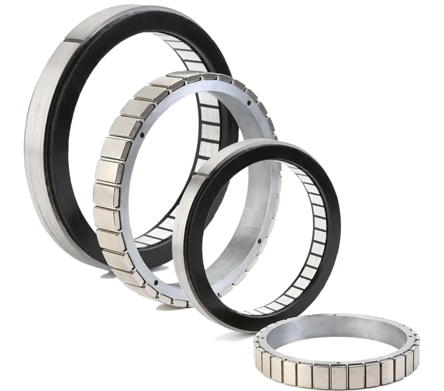
In short:Pick a frameless rotor and stator kit when you can hold the air gap with your own bearings and housing and want the lightest, most compact axis; pick a housed direct-drive motor when you want bearings and encoder already aligned. Then size on peak and RMS torque, compare candidates by motor constant Km, design the stator's heat path, and fix the bore, feedback and commutation method before the housing is drawn.
The decisions, in order
A frameless torque motor is a rotor and a stator with no shaft, bearings or housing. It becomes part of your machine: a robot joint, a rotary table, a gimbal, a spindle or a pump. Because the machine now holds the air gap and carries the heat, selection is as much a mechanical design job as an electrical one. Work through it in this order:
- Kit or housed: frameless, or a housed direct-drive motor with its own bearings and encoder.
- Torque and speed: peak, RMS and top speed at the load, with the gear ratio if any.
- Efficiency and heat: compare by Km, then design the heat path out of the stator.
- Construction: slotted iron-core, or slotless/ironless where cogging must be zero.
- Geometry: outer diameter, stack length and bore.
- Mounting: concentricity, housing fit, bonding or clamping, assembly fixtures.
- Feedback and commutation: encoder type and location, Halls or encoder commutation.
- Drive and voltage: bus voltage, winding, current and thermal protection.
If the axis is a robot or cobot joint with a strain-wave gear, our frameless motor sizing guide for robot joints goes deeper on the torque budget, gear ratio trade-off, dual encoders and brakes. This guide covers the selection steps that apply to every frameless and direct-drive axis.
Step 1: frameless kit vs housed direct drive
| Factor | Frameless kit | Housed direct-drive motor |
|---|---|---|
| What you get | Stator and rotor (often with Halls, thermal sensor) | Motor, bearings, housing and encoder, aligned and tested |
| Mass and length | Lowest; shares your bearings and structure | Higher; has its own bearings and covers |
| Air gap | You hold it | Held by the maker |
| Encoder | You choose, mount and align | Fitted, often SIN/COS optical or absolute |
| Design risk | Higher: tolerances, assembly, magnetic pull | Lower: bolt it on and couple the load |
| Typical uses | Robot joints, gimbals, actuators, sealed or vacuum assemblies | Rotary tables, indexers, inspection stages, test rigs |
Choose a kit when mass, length or a shared structure matters most, or when the motor must sit inside a sealed or unusual housing. Choose a housed direct drive when you need it working quickly, the load can sit on the motor’s own bearing, and you would rather not design for 0.05 mm concentricity yourself.
Step 2: torque and speed at the load
Without a gearbox, the motor sees the load’s full inertia and torque. Build the cycle from the motion profile:
- Peak torque = (J_load + J_rotor) × α + friction + gravity
- RMS torque = √( Σ Tᵢ² tᵢ / Σ tᵢ ), including dwell time at holding torque
The peak must sit inside the motor’s peak rating with margin (allow 20–30% as a rule of thumb for tuning and supply sag). The RMS must sit inside the continuous rating in your mounting, not the catalogue’s test mounting. Kollmorgen, for example, quotes TBM continuous ratings at 25 °C ambient with the motor housed and mounted to a defined heatsink plate (Kollmorgen TBM).
Check top speed against the winding: the back-EMF at maximum speed plus the I×R drop must fit under the drive’s bus voltage. Most kits come in low-speed and high-speed windings for the same frame, so pick the winding after the bus voltage is fixed.
Step 3: compare by Km, then design the heat path
The motor constant Km is torque per square root of copper loss:
Km = T / √P_copper = Kt / √R (Nm/√W)
and therefore P_copper = (T / Km)².
Alva Industries points out that if Kt is quoted per Arms, R must be the three-phase equivalent resistance, 1.5 × the line-to-line value, and that Km describes copper loss only, so it is most useful at stall and low speed, where other losses are small (Alva via UST). Use the hot Km (at winding temperature) for sizing: resistance rises with temperature, so Km falls. Kollmorgen, for instance, lists Km at 25 °C and at a 155 °C winding temperature (Kollmorgen TBM).
Why diameter wins. Torque scales with the air-gap radius, so a short, large-diameter motor usually gives more Km than a long, thin one of the same mass. That is why direct-drive and joint motors look like rings.
The heat path is your design. Almost all copper loss is generated in the stator. It must cross the stator-to-housing interface, the housing, and then reach air, a cold plate or the structure. Thermal resistance in °C/W per path element determines the winding temperature rise:
ΔT = P_copper × R_th
Bonding the stator with a void-free adhesive or a press fit, and making the housing from aluminium with a short path to a cooled surface, can make more difference than choosing a larger motor. Alva recommends keeping housing metal 2–3 mm from the end-turns for insulation, and pre-heating the housing to 100 °C or more for bonding (Alva via UST). Fit a thermal sensor in the winding and wire it to the drive.
Step 4: slotted iron-core vs slotless or ironless
- Slotted iron-core frameless motors give the highest torque density and Km. They have some cogging: Kollmorgen’s TBM data works out at roughly 1–3% of continuous stall torque peak to peak (Kollmorgen TBM). They also have strong magnetic attraction during assembly.
- Slotless and ironless designs have no teeth, so no cogging, lower velocity ripple and less sensitivity to radial misalignment (Alva via UST), but less torque for their size.
Choose zero-cogging designs for slow, smooth scanning (optical inspection, metrology, camera gimbals) where velocity ripple shows up in the result. For most robot joints and indexers, a slotted motor with a well-tuned drive is fine.
Step 5: bore, diameter and stack
The bore is the rotor ID. It must clear the cables, slip ring, fluid lines or optics that pass through, plus the shaft wall and encoder. Fix it early: it constrains the bearing, the encoder ring and the housing. Then pick the outer diameter for Km and the stack length for torque. Allow axial space for end-turns, leads and the thermal sensor, which make the stator longer than the active laminations.
Step 6: mounting and air-gap tolerances
The air gap in a frameless motor is small, and your parts set it. Typical guidance from Kollmorgen (Kollmorgen):
- Concentricity between rotor ID and stator OD of 0.002 in (about 0.05 mm), 0.004 in TIR (about 0.10 mm)
- Housing bore 0.001 to 0.002 in (about 0.025 to 0.05 mm) larger than the stator OD for a bonded stator
- Shaft 0.001 to 0.002 in under the rotor ID, held to ±0.001 in, for a bonded or clamped rotor
- Diametrical clearance at the axial locating shoulder of at least 0.020 in for most models
Alva gives similar practical detail: 0.2–0.3 mm deep adhesive grooves over 50–75% of the stator length, at least half of the stator back-iron engaged by any axial clamp, and keeping loose magnetic items about three rotor diameters away during handling (Alva via UST).
The rotor is strongly attracted to the stator. Plan an assembly fixture or a guided insertion that keeps the parts concentric until the bearings take over, and a non-magnetic sleeve if the maker recommends one. Stack up bearing clearance, housing runout and thermal growth to confirm the minimum gap under load and temperature.
Step 7: encoder integration and commutation
Encoder choice. A direct-drive axis has no ratio to divide encoder error, so the encoder sets the axis accuracy directly. A ring or kit encoder must be centred on the axis: for a ring, RLS gives the eccentricity error as ±0.114 × e / D degrees, with e in µm and D in mm (RLS). On a 100 mm ring, 10 µm of eccentricity gives about ±0.011° (±41 arcsec). Hollow capacitive and inductive encoders that average over the whole circumference are more tolerant of mounting error. See our encoder selection guide.
Commutation. The drive must know rotor electrical angle:
- Hall sensors: simple and robust; many kits offer them pre-aligned. Kollmorgen’s TBMS, for example, uses latching Hall effect devices on a 5–24 VDC supply (Kollmorgen TBM).
- Absolute encoder: commutation from the encoder after a one-off offset is stored. No Halls needed.
- Incremental encoder without Halls: the drive must run a phase-finding routine at power-up, which moves or vibrates the axis. Not acceptable on a loaded vertical axis or a joint with a brake engaged.
Confirm that the drive supports the encoder protocol and the commutation method before the housing is drawn. See absolute vs incremental encoders.
Worked example: direct-drive indexing table
Requirement: Inspection indexing table, load inertia 0.5 kg·m². Each 90° index in 0.25 s (triangular profile), then 0.5 s dwell for imaging. Friction about 2 Nm. Stations must repeat to ±10 µm at 150 mm radius. A 60 mm bore is needed for a slip ring and vacuum line.
Kinematics (θ = 1.571 rad, t = 0.25 s):
- α = 4θ / t² = 4 × 1.571 / 0.0625 = 100.5 rad/s²
- Peak speed ω = 2θ / t = 12.6 rad/s = 120 rpm
Torque: 0.5 × 100.5 = 50.3 Nm, plus 2 Nm friction, gives 52 Nm accelerating and about 48 Nm decelerating (friction helps). Add the rotor and table-top inertia once a candidate is chosen.
RMS torque: √( (52² × 0.125 + 48² × 0.125) / 0.75 ) = 28.9 Nm.
Copper loss: for an illustrative hot Km of 3 Nm/√W, P = (28.9 / 3)² ≈ 93 W. If the housing-to-air path is 0.5 °C/W, the stator runs about 46 °C above ambient. Doubling Km would cut the loss to about 23 W. This is why Km, not just continuous torque, decides the size.
Construction: imaging during dwell, not during motion, so cogging is less critical; a slotted motor is acceptable. If the camera imaged during rotation, a zero-cogging ironless motor would be the better choice.
Kit or housed: the table top can sit on a cross-roller bearing designed into the base, but the team wants the encoder aligned at the factory. A housed direct-drive motor with a large centre hole and a built-in encoder is the lower-risk route.
Encoder: ±10 µm at 150 mm is ±67 µrad, about ±14 arcsec. Because stations repeat, repeatability matters more than absolute accuracy, and station positions can be taught. A high-resolution optical or absolute encoder fitted by the motor maker meets it; a ring fitted by hand would need tight centring or two read heads.
Candidates: a housed motor from the Akribis ADR-A or AXD ranges (centre holes up to 60 mm and 130 mm respectively), checked for 52 Nm peak and 29 Nm continuous at the actual mounting. The AXD’s 130 mm maximum bore gives more room for the slip ring.
Products in our range to consider
- Akribis ADR-F: compact 48 VDC frameless kits, 45–90 mm OD, up to 11.2 Nm peak.
- Akribis ADR-P: 600 VDC frameless kits, 110–360 mm OD, bores to 229 mm, up to 985 Nm peak, Halls fitted.
- TI Series in-runner frameless torque motors: 65–410 mm stator OD, 8–64 poles, through-holes to 290 mm.
- Akribis ADR-A: housed iron-core direct drive with optical encoder, up to about 1,018 Nm peak.
- Akribis AXD: low-profile housed direct drive, 80–400 mm frames, centre holes to 130 mm.
- Akribis AXD-ERA: AXD with a 23-bit BiSS-C absolute encoder resistant to contamination.
- Akribis ACD: ironless housed direct drive with zero cogging, up to 32 Nm peak.
- Akribis ACW: flat ironless direct drive with large centre holes and zero cogging, to 400 rpm.
What else the build needs
- Servo drive matched to bus voltage, winding current, encoder protocol and commutation method. See servo drives.
- Feedback: a ring, kit or hollow-shaft encoder, and sometimes a second encoder after a gear. See encoders.
- Bearings and structure: a cross-roller or angular-contact pair to hold the air gap and the load.
- Gearing if the torque is too high for direct drive: see gearboxes and the strain-wave vs planetary vs cycloidal comparison.
- Brake for vertical or gravity-loaded axes.
- Slip ring for continuous rotation through the bore: see slip rings and how to select a slip ring.
- Controller for coordinated motion: see motion controllers.
Things that catch engineers out
- Using catalogue continuous torque without the catalogue heatsink. Your housing may hold far less heat.
- Using cold Km. Size on the hot value.
- Underestimating magnetic pull during assembly. Without a fixture, rotors snap to stators and damage magnets or fingers.
- Tolerance stack-ups that close the gap. Bearing play, runout and thermal growth add up.
- Phase-finding at power-up on an axis that cannot move freely.
- Leaving the bore until last. It sets the bearing, encoder and slip ring sizes.
- No thermal sensor wired to the drive. A frameless stator can overheat quietly inside a sealed joint.
Checklist
Send these to our engineers, or enter them in the spec builder:
- Kit or housed, and why (mass, length, sealing, assembly)
- Load inertia, friction and gravity torque
- Motion profile: moves, times, dwell, and the resulting peak and RMS torque
- Top speed and the drive bus voltage
- Envelope: maximum OD, axial length, and required bore
- Heat path: housing material, cooling method, ambient temperature
- Cogging or velocity ripple limits
- Encoder type, resolution and accuracy needed; Halls or encoder commutation
- Drive make and model if already chosen
- Environment: vacuum, washdown, IP rating, shock and vibration
- Quantity and production timing
For the wider family, see our frameless and direct-drive torque motors overview.
Frequently asked questions
What is the difference between a frameless motor and a housed direct-drive motor?
A frameless motor is just a stator and a rotor. Your machine supplies the shaft, bearings, housing and feedback, and holds the air gap. A housed direct-drive motor (often called a torque motor or DD motor) comes with its own bearings, housing and usually an encoder, aligned and tested. Frameless saves mass and length and lets the motor become part of the structure; housed saves design and assembly risk.
What is the motor constant Km?
Km is torque per square root of copper loss, in Nm/√W. It equals Kt/√R under the right conventions; if Kt is per Arms, Alva Industries notes that R must be the three-phase equivalent of 1.5 × the line-to-line resistance. Copper loss at a given torque is (T/Km)², so a motor with twice the Km runs with a quarter of the heat for the same torque.
What causes cogging in a torque motor and how do I reduce it?
Cogging is the torque ripple from magnets aligning with stator teeth, present even with no current. Slotted iron-core motors have some; manufacturers reduce it with skewing and pole-slot combinations. Kollmorgen's TBM data, for example, puts peak-to-peak cogging at roughly 1–3% of continuous stall torque. Slotless or ironless designs have effectively none, at the cost of lower torque density.
How accurately do I need to align a frameless rotor and stator?
Follow the maker's drawing, but expect tight numbers. Kollmorgen's frameless mounting guidance calls for 0.002 in (about 0.05 mm) concentricity between rotor ID and stator OD, 0.004 in TIR, and a housing bore 0.001 to 0.002 in larger than the stator OD. Eccentricity causes unbalanced magnetic pull, torque ripple and, at worst, rub.
Do I need Hall sensors on a frameless motor?
Only if the drive needs them to commutate. Many kits offer factory-aligned Halls; Kollmorgen's TBMS, for example, uses latching Hall devices. With an absolute encoder, most modern drives commutate from the encoder after a one-off phase offset, so Halls become optional. With an incremental encoder and no Halls, the drive must run a phase-finding routine at every power-up.
Can a frameless motor have a large hollow bore?
Yes, that is one of the main reasons to use one. Bore size is set by the rotor's inner diameter, so ring-shaped motors with large bores are common; the ADR-P kits in our range go up to a 229 mm rotor ID. A larger diameter also gives more torque per unit of copper, because torque scales with air-gap radius.
Sources
- Kollmorgen: Mounting design and installation of frameless motors
- Kollmorgen: TBM frameless motor selection guide
- Alva Industries via Unmanned Systems Technology: Why motor constant Km matters
- Alva Industries via Unmanned Systems Technology: Installing and mounting a frameless motor
- RLS: Accuracy of the ring encoder (eccentricity error)
Figures are summarised from the sources above and from manufacturers' published data on the date shown. Always confirm against the current datasheet for your exact part.