
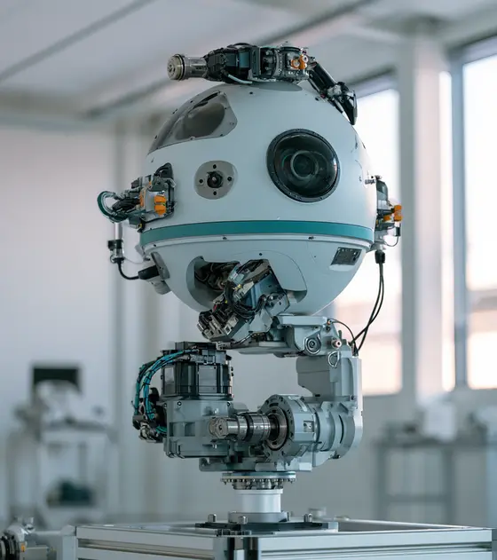
In short:EO/IR and surveillance gimbals hold a sensor's line of sight steady while the platform moves, so every axis is built around direct-drive, low-cogging frameless motors, axis-mounted high-resolution absolute encoders and, for continuous rotation, a low-drag slip ring that carries HD video and Ethernet. Specify torque, stiffness, sensor noise and data rate from the stabilisation requirement down.
Typical requirements
| EO/IR slip ring data | Up to about 24 channels at over 400 Mbit/s each; GigE, Fibre Channel, IEEE 1394 |
|---|---|
| Direct-drive gimbal stage encoder (example) | 26-bit absolute (67,108,864 counts/rev), BiSS-C |
| Static pointing accuracy (example) | 0.01° at 25 °C |
| Operating temperature (example gimbal stage) | −54 °C to +71 °C; slip ring rated to 50,000 ft (about 15,200 m) |
| Gimbal slew rate (examples) | 60 °/s (maritime pan-tilt) to 200 °/s (UAV gimbal) |
| Stabilisation (maritime pan-tilt example) | Under 2 mrad RMS |
Machinery we specify motion for
- Airborne EO/IR sensor pods
- UAV camera gimbals
- Vehicle-mounted sights and sensor heads
- Naval mast-mounted EO/IR positioners
- Fixed-tower surveillance pan-tilt units
- Imager and rangefinder mounts
EO/IR gimbals carry daylight cameras, thermal imagers, laser rangefinders and other sensors on aircraft, UAVs, vehicles, ships, masts and fixed towers. Small UAV gimbals weigh a few hundred grams; airborne sensor pods and ship or vehicle sights are far larger. The motion problem is the same in all of them: keep the line of sight still in inertial space while the platform vibrates, manoeuvres and rolls, and point it accurately on command. That puts extreme demands on smoothness, stiffness and feedback, and much less on raw speed.
Direct-drive frameless motors and low cogging
Most stabilised gimbals use direct-drive brushless torque motors on every axis. Kollmorgen’s EO/IR systems page makes the case: a direct-drive motor attached to the load reduces size, weight, power and response time, and its frameless kits (RBE, TBM, KBM) remove shaft, bearings, endbells and couplings so the motor becomes part of the gimbal structure. Kollmorgen’s TBM2G gimbal notes add that frameless motors can be made with short axial length across a range of diameters, and that a winding temperature sensor is worth fitting at the prototype stage to check heating at peak torque.
How to choose:
- Slotted vs slotless. Slotted frameless motors give the highest torque density; slotless and ironless designs give near-zero cogging for very smooth slow tracking. Ironless housed direct drives such as the Akribis ACD show the zero-cogging end of the spectrum; low-voltage frameless kits such as the Akribis ADR-F suit compact axes.
- Torque sizing. Peak torque = inertia × peak angular acceleration needed to reject the disturbance, plus friction, slip ring and cable drag, and imbalance. Continuous torque is set by the RMS of the disturbance-rejection torque over the mission.
- Diameter and bore. A larger air-gap diameter gives more torque per unit mass and a bigger hollow centre for cables and slip rings.
- Voltage. Match the winding to the platform bus. Moog’s AC7332 gimbal stage, for instance, has a 22 V or 30 V stall voltage with windings available to 96 V or 144 V.
See frameless torque motors and frameless motor sizing.
Slip rings with HD video and Ethernet
Continuous azimuth rotation on a gimbal or pod requires a slip ring that adds as little drag and noise as possible while carrying more and more data. Moog’s electro-optic (EO/IR) slip rings carry up to about two dozen channels at over 400 Mbit/s each, around 12 Gbit/s in aggregate, for GigE, Fibre Channel and IEEE 1394, with slip ring and fibre optic rotary joint hybrids where fibre is needed. They are sealed, EMI-shielded and built for high shock and vibration.
For smaller payloads, the Moog AC7332 direct-drive gimbal stage shows a typical integrated slip ring: 17 signal rings plus 2 power rings (20 A peak, 2 A continuous), 50 V DC maximum, rated to 50,000 ft altitude, with twisted-pair leads for gigabit Ethernet. Miniature gold-on-gold capsules such as Moog’s AC264 family carry 20–60 low-current circuits for UAV gimbals.
When specifying a UAV gimbal slip ring or pod slip ring, state each data protocol and rate, video format (HD-SDI, Ethernet video, analogue), impedance, power per ring, speed, drag torque limit, altitude and temperature. Read Ethernet through slip rings, Ethernet slip rings, fibre optic rotary joints and gimbal and drone slip rings.
High-resolution encoders
Each axis needs absolute position feedback mounted directly on the axis. Kollmorgen recommends a 20-bit or higher encoder, or a resolver, for closed-loop control of its frameless gimbal motors, with Hall tracks or sensors for commutation. The AC7332 uses a 26-bit optical absolute encoder on BiSS-C and quotes 0.01° static pointing accuracy at 25 °C; its encoder is screened to −54 °C and heated briefly before power-up below −40 °C. Capacitive and inductive kits are thinner and tolerate contamination: Netzer’s VLT covers −55 °C to +125 °C, and inductive Mini Ultra IncOder units suit small hollow-shaft axes. Compare in absolute vs incremental encoders.
Line-of-sight stabilisation at component level
The stabilisation loop uses an inertial rate sensor (gyro) to measure platform motion and drives the motors to cancel it; the encoder handles commutation, position reporting and pointing. Published figures give a sense of range: General Dynamics OTS quotes under 2 mrad RMS stabilisation for its Vector 20 maritime pan-tilt with 0.01–60 °/s slew; Allied Motion describes a UAV gimbal with 200 °/s slew and continuous pan.
Component requirements that follow:
- Stiff structure and direct coupling. The first resonance must sit well above loop bandwidth.
- Low torque ripple and cogging.
- Fast current loop. Compact drives that close the current loop at high frequency, such as the Novanta Capitan, fit inside the gimbal; see servo drives.
- Consistent, low drag from slip rings, cables and seals across temperature.
- Low-latency, low-noise feedback.
Environment and EMC
- Temperature and altitude. The AC7332 example operates from −54 °C to +71 °C at up to 95% humidity. Airborne pods add low pressure (MIL-STD-810H Method 500) and rapid temperature change (503).
- Vibration. Airframe and vehicle vibration is the disturbance the gimbal exists to reject, and it also stresses bearings, brushes and encoder mounts. Test to the tailored MIL-STD-810H Method 514 profile or DO-160 for airborne equipment.
- Ingress. Vehicle and naval gimbals need IP67-class sealing, salt fog (Method 509) and sand and dust (510) resistance.
- EMC. MIL-STD-461 or DEF STAN 59-411. Sensitive imaging electronics sit centimetres from PWM motor drives; shield phase leads and separate power and signal rings in the slip ring.
- Export control. EO/IR gimbals and their specially designed components are often controlled; see the defence and security overview.
Typical pitfalls
- Using a geared motor on a stabilised axis and fighting backlash.
- Specifying encoder bits rather than accuracy and noise.
- Ignoring slip ring drag change at low temperature.
- Routing unshielded motor leads past the sensor electronics.
- Not budgeting bandwidth growth in the slip ring for the next sensor upgrade.
- Forgetting cable wrap stiffness on limited-travel inner axes, which adds a position-dependent torque the loop must fight.
For component-level platforms, see also military drones and UAVs and counter-UAS systems. Send your axis inertias, stabilisation target and data requirements, and our specialist engineering and supply partners can propose motors, slip rings, encoders and drives.
EO/IR gimbal motors
Stabilised gimbals use direct-drive brushless torque motors on every axis, usually frameless kits that become part of the gimbal structure. Slotted kits give the most torque per unit mass; slotless and ironless designs give near-zero cogging for the smoothest slow tracking. Size peak torque from inertia times the angular acceleration needed to reject the platform disturbance, plus friction, slip ring and cable drag and imbalance, and continuous torque from the RMS of that disturbance over a mission. A larger air-gap diameter gives more torque per kilogram and a bigger bore. Specify the winding for the platform bus and fit a winding temperature sensor on prototypes.
- Airborne sensor pods: stabilised direct-drive axes
- UAV gimbals: compact low-mass frameless kits
- Vehicle and naval sights: low-cogging pan and tilt
- Fixed-tower pan-tilt units: smooth slow tracking
Available through our supply network
All frameless and torque motors →Specify frameless and torque motors for eo/ir gimbals and targeting pods →
Slip rings for EO/IR pods and gimbals
Continuous azimuth on a pod or gimbal needs a slip ring that carries more data every sensor generation while adding as little drag and noise as possible. State each data protocol and rate, video format (HD-SDI, Ethernet video or analogue), impedance, power per ring, speed, drag torque limit, altitude and temperature. Electrical channels with controlled impedance carry gigabit Ethernet and HD video; fibre and electrical hybrids take over when copper runs out. Separate power and signal rings and shield them, because imaging electronics sit centimetres from motor drives. Check drag at low temperature, where it rises, and leave spare bandwidth for the next sensor upgrade.
- Airborne EO/IR pods: high-bandwidth hybrid slip rings
- UAV gimbals: low-drag capsules for continuous pan
- Vehicle sensor heads: HD video and Ethernet rings
- Naval positioners: sealed rings with fibre channels
Available through our supply network
All slip rings →Specify slip rings for eo/ir gimbals and targeting pods →
High-resolution encoders for EO/IR gimbals
Each gimbal axis needs absolute feedback mounted directly on the axis for commutation, position reporting, pointing to coordinates and limits, while the gyro handles inertial stabilisation. Kollmorgen recommends 20-bit or higher encoders, or a resolver, for closed-loop control of its frameless gimbal motors. Look beyond bit count: accuracy, noise, latency and mounting stiffness decide how well the axis points. Capacitive and inductive kits are thin and tolerate contamination; optical encoders reach the highest resolution but may need heating before power-up in deep cold. Specify bore, interface (BiSS-C or SSI), update rate, temperature range including cold start, and shock and vibration ratings.
- Gimbal pan and tilt axes: absolute high-resolution feedback
- Inner stabilised axes: thin hollow encoders
- Sensor pods: pointing to commanded coordinates
- Naval and vehicle sights: rugged axis feedback
Available through our supply network
All encoders and feedback →Specify encoders and feedback for eo/ir gimbals and targeting pods →
Servo drives for gimbal stabilisation
The drive sets how quickly a gimbal axis can respond to the rate command from the stabilisation loop, so a fast current loop and low current noise matter more than raw power. Compact drives that close the current loop at high frequency fit inside the gimbal body and shorten the motor leads. Specify input voltage, continuous and peak current per axis, encoder interfaces, network and update rate, mass and footprint. Low-inductance gimbal motors need a high PWM frequency to keep ripple down. Shield phase leads and keep them away from sensor electronics, because PWM noise couples straight into imaging and fails MIL-STD-461 emissions tests late in a programme.
- UAV gimbals: board-level stabilisation drives
- Airborne pods: compact multi-axis drives
- Vehicle sensor heads: rugged high-bandwidth drives
- Fixed surveillance positioners: networked axis drives
Available through our supply network
All servo drives →Specify servo drives for eo/ir gimbals and targeting pods →
Voice coil actuators for focus and fine adjustment
Inside the sensor, short-stroke mechanisms move lenses for focus, adjust optical elements and position filters. Voice coil actuators suit these jobs: they have no cogging, very low moving mass and no commutation, so they move quickly and smoothly over a few millimetres to a few tens of millimetres with simple drive electronics. Specify stroke, force, moving mass, required bandwidth, position feedback and the heat the coil adds next to the optics, since warming a lens barrel shifts focus. Flat voice coils build into thin stages; cylindrical types suit axial focus. Check the shock and vibration ratings of the guide or flexure as well as the coil.
- Imager focus mechanisms: fast smooth lens positioning
- Optical adjustment stages: short-stroke fine motion
- Filter and shutter mechanisms: quick linear moves
- Rangefinder and imager alignment: precise small strokes
Available through our supply network
All linear actuators →Specify linear actuators for eo/ir gimbals and targeting pods →
Small motors for filter wheels and lens drives
Gimbal payloads also contain small rotary mechanisms: filter wheels, zoom and focus rings, shutters and calibration flags. Piezo motors hold position with power off and give fine steps without a gearbox, which suits precision optics. Slotless brushless motors run smoothly with no cogging and long life, and small stepper motors give low-cost open-loop positioning where holding torque and a home sensor are enough. Specify torque, speed, step or position resolution, holding with power off, temperature range, outgassing near optics, and magnetic field near sensitive detectors. Check mass and supply voltage against the payload budget, and test behaviour after cold soak.
- Filter wheels: indexed rotary positioning
- Zoom and focus rings: fine rotary adjustment
- Shutters and calibration flags: quick small moves
- Optics positioning: power-off holding with piezo motors
Available through our supply network
All servo and stepper motors →Specify servo and stepper motors for eo/ir gimbals and targeting pods →
Standards to have in view
- MIL-STD-810H (environmental engineering and laboratory tests)
- MIL-STD-461H (control of electromagnetic interference; supersedes MIL-STD-461G)
- RTCA DO-160 (environmental conditions and test procedures for airborne equipment)
- DEF STAN 00-35 (environmental handbook for defence materiel)
- DEF STAN 59-411 (electromagnetic compatibility)
- IEC 60529 (IP codes)
Which standards apply depends on the end product and its market. Your engineer will confirm what the component itself needs to meet.
Frequently asked questions
What motor is best for an EO/IR gimbal?
Usually a direct-drive brushless torque motor, often a frameless rotor and stator kit built into the gimbal yoke. Direct drive removes backlash and gear compliance, which limit stabilisation, and the frameless format saves mass and leaves a hollow centre for cables, slip rings or optics. Choose a low-cogging or slotless design for smooth slow tracking, and size it for peak acceleration under the platform's disturbance spectrum.
Why does cogging matter so much on a gimbal?
Cogging torque is a position-dependent ripple caused by magnets aligning with stator teeth. At slow tracking rates the control loop has to fight it continuously, and any residual shows up as jitter in the image. Slotless and ironless motors have essentially zero cogging; slotted motors reduce it with skew and pole and slot combinations. Ask the supplier for measured cogging and torque ripple, not just a qualitative claim.
What does a UAV gimbal slip ring need to carry?
Power for the sensors and inner-axis motors, control signals, and the sensor data. Modern EO/IR payloads send HD video and Ethernet, so the slip ring needs controlled-impedance channels or a fibre optic rotary joint. Moog's EO/IR slip rings carry up to about two dozen channels at over 400 Mbit/s each. Keep drag torque low and consistent, as it acts directly on the stabilised axis.
How much encoder resolution does a gimbal need?
Enough that quantisation is well below the pointing and jitter budget, with low noise and latency. A 26-bit absolute encoder resolves about 0.02 arcseconds per count; Kollmorgen recommends a 20-bit or higher encoder or a resolver for closed-loop control of its frameless gimbal motors. Accuracy, noise and mounting stiffness matter as much as the bit count.
Can the gyro alone stabilise the line of sight?
The gyro measures inertial rate and is the main stabilisation sensor, but the axis also needs an encoder for commutation, position reporting, pointing to coordinates and limits. Performance then depends on the whole chain: gyro noise and bandwidth, motor torque ripple, structural stiffness, slip ring and cable drag, and current loop bandwidth in the drive.
What should I send for an EO/IR gimbal component enquiry?
Send the number of axes and their ranges, payload mass and inertia per axis, slew rate and acceleration, stabilisation and pointing targets, the platform disturbance spectrum, envelope and mass budget, signals and data that cross each rotating axis, supply voltage, temperature, altitude, ingress, shock, vibration and EMC requirements, and production volume.
Sources
- Moog: aerospace and defence slip ring product catalogue (electro-optic slip rings)
- Moog: rotary gimbal stage AC7332 datasheet
- Kollmorgen: electro-optical infrared systems
- Kollmorgen: TBM2G frameless motors for gimbal precision
- Allied Motion: motion control solutions for military aircraft
- General Dynamics OTS: Vector 20 stabilised maritime pan-tilt system
- Netzer: product catalogue 2025
Figures are summarised from the sources above and from manufacturers' published data on the date shown. Always confirm against the current datasheet for your exact part.