
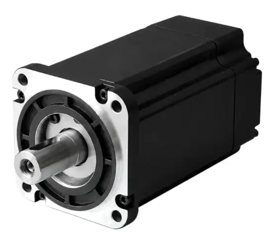
In short:Choose the supply class first (mains AC or 24–96 V DC), then size from the move profile: RMS torque must sit inside the motor's continuous rating and every peak inside the intermittent zone at its speed. Keep the reflected inertia within roughly 5 to 10 times the rotor, then pick feedback, brake, sealing and a drive matched to the motor's current.
The selection sequence
Servo selection is iterative, because the motor’s own inertia feeds back into the torque it needs (Kollmorgen). Work in this order:
- Choose the supply class: mains AC or low-voltage DC.
- Build the move profile and choose the transmission (direct, gearbox, belt, screw).
- Calculate torque for every segment of the cycle and the peak.
- Calculate RMS torque and check it against the continuous rating at the RMS speed.
- Check peak torque at speed against the intermittent zone, and maximum speed.
- Check the inertia ratio, and change the ratio or motor if needed.
- Choose feedback, brake, sealing, shaft and connectors.
- Match the drive: current, voltage, feedback protocol, fieldbus, safety.
If you are still deciding between a servo and a stepper, see servo vs stepper.
AC servo vs low-voltage DC servo
| AC servo (mains-fed) | Low-voltage DC servo | |
|---|---|---|
| Supply | 1ph/3ph 200–240 V AC, or 3ph 380–480 V AC | 24–96 V DC, often battery |
| DC bus | Roughly 300 V or 560 V | Equal to supply |
| Power range (typical catalogue) | 50 W to several kW, and beyond | Tens of watts to a few kW |
| Current for a given power | Low | High: cables, connectors and contactors grow |
| Typical use | Packaging, machine tools, fixed automation | AGVs, AMRs, mobile robots, battery equipment, SELV machines |
Both are normally permanent-magnet synchronous (brushless) motors; the difference is the winding and the drive. Brushed DC servos with tachogenerators still exist for retrofits and simple analogue loops, but new designs are almost always brushless.
The deciding factor is current. Power is voltage × current, so a 1 kW axis on a 48 V supply draws over six times the current of the same axis on a roughly 320 V DC bus. As power per axis rises on a low-voltage system, cable size, voltage drop and connector ratings quickly start to drive the design.
Continuous vs peak torque, and RMS
A servo’s torque-speed curve has two zones (Linear Motion Tips):
- Continuous zone: torque the motor can deliver indefinitely without overheating. The RMS torque of your cycle must sit here.
- Intermittent zone: torque available for short periods. Every peak point (torque at the speed it occurs) must sit here, as must the maximum speed.
Both zones shrink at higher speed, because back-EMF eats into the drive’s voltage headroom. A curve is valid only for the motor-drive pairing and supply voltage it was measured with.
RMS torque is the thermal equivalent of the whole cycle, including dwells (Kollmorgen):
T_rms = √( Σ Tᵢ² × tᵢ / Σ tᵢ )
Each segment’s torque is the sum of:
- Acceleration: (J_motor + J_gearbox + J_load reflected) × α
- Friction and process load reflected to the motor: T ÷ (i × η) through a gearbox of ratio i
- Gravity on vertical or inclined axes, including during dwells
- Holding torque during dwells if the motor, not a brake, holds the load
For peaks, note the drive’s limits as well as the motor’s. Kollmorgen notes typical amplifiers give two times peak current for 2 to 8 seconds; if your peak lasts longer, check the motor’s thermal time constant too.
Speed and winding
The maximum speed of the cycle must be inside the motor’s rated or maximum speed and, with gearing, inside the gearbox’s input speed limit; Kollmorgen cites 3,000 to 4,000 rpm for many gearboxes. Choose the lowest-speed winding that meets the application: higher-speed windings have a lower torque constant, so they need more current and a larger, costlier drive for the same torque (Kollmorgen).
On a screw axis, motor speed = linear speed ÷ lead. On a belt axis, motor speed = linear speed ÷ travel per pulley revolution × gearbox ratio.
Inertia ratio
The inertia ratio is reflected load inertia (plus gearbox) divided by rotor inertia. Kollmorgen’s guide recommends keeping it at or below about 5:1 and suggests a higher-inertia motor above that (Kollmorgen). Other sizing guidance uses 10:1 or lower, and points out there is no single correct number: compliant drive trains with belts and couplings need lower ratios, and a ratio near 1:1 usually means an oversized motor (Motion Control Tips).
Reflected inertia through a ratio i is J_load ÷ i². For a linear load of mass m on a pulley of radius r, J = m × r²; on a screw of lead P, J = m × (P ÷ 2π)².
Many servo ranges come in low-inertia and medium- or high-inertia versions of the same frame. If the ratio is high but torque is fine, try the higher-inertia version before stepping up a frame.
Feedback resolution
Current AC servos commonly carry 17-bit (131,072 counts per revolution) to 23-bit (8,388,608 counts per revolution) absolute encoders, as in the ranges in our catalogue data. Higher resolution lets the drive run higher position and velocity loop gains and gives smoother low-speed motion (Kollmorgen). Decide on:
- Single-turn or multi-turn absolute: multi-turn avoids homing after power-up.
- Battery-backed or battery-less multi-turn: battery-less avoids a maintenance item.
- Optical or magnetic: optical for the finest resolution, magnetic for robustness and cost.
- Resolver: very robust for heat, shock and vibration, at lower accuracy.
- Protocol: it must match the drive, for example BiSS-C, EnDat, HIPERFACE, Tamagawa or a maker’s own serial protocol.
See absolute vs incremental encoders for more.
Brakes
Servo motor brakes are almost always spring-applied, power-off holding brakes. They hold a stopped vertical or back-drivable axis when the drive is disabled or power fails. Machine Design suggests a static rating about 50% above the worst-case holding torque, notes that the motor must hold the load until the brake engages (tens of milliseconds in their example), and warns that static brakes used dynamically often fail (Machine Design).
A brake adds length, inertia and a 24 V supply and control output. It is required on vertical axes and on screws that can back-drive. It is not a safety function by itself; if people can be under the axis, the brake control belongs in the machine’s safety design.
IP rating and environment
Check the IP rating of the body and the shaft separately. Some ranges in our catalogue data are IP67 on the body but IP54 at the shaft with an oil seal, and IP50 without one. If coolant, washdown water or dust reaches the shaft end, specify the shaft seal or protect it mechanically. Also check:
- Ambient temperature, and derating above the rated ambient
- Mounting surface: the flange is part of the motor’s heat path, so ratings usually assume an aluminium or steel plate of stated size
- Connector type and orientation: rotatable connectors save cable strain
- Food-grade, stainless or hygienic versions if the motor is in the splash zone
Cabling
- Motor power and feedback cables must suit the drive’s switching. Long cables between inverter drives and motors can cause reflected-wave voltage overshoot at the motor terminals. Fluke gives 1,000 V peak and 500 V/µs as limits below which 400 V motor insulation is not significantly stressed, and notes du/dt chokes can extend usable cable length from 30 m to up to 100 m depending on switching frequency (Fluke). Check your servo drive’s maximum cable length.
- Single-cable (hybrid) technology puts feedback in the power cable; it saves a cable chain slot but must be supported by both motor and drive.
- Flex life: specify continuous-flex cable rated for the cable chain bend radius and cycle count.
- Low-voltage systems need large cross-sections; calculate voltage drop at peak current.
Matching the drive
- Continuous and peak current cover the motor’s needs. Kollmorgen advises against an oversized drive whose continuous current exceeds the motor’s continuous rating.
- Voltage class matches the motor winding (230 V, 400 V, or the DC bus range).
- Feedback protocol matches the encoder.
- Command interface: EtherCAT, PROFINET, EtherNet/IP, CANopen, Modbus, pulse/direction or analogue.
- Safety: STO to the SIL or PL your risk assessment needs; brake control output.
- Regeneration: a braking resistor or shared DC bus if the axis decelerates large inertia or lowers loads often.
Usually the cleanest answer is a motor and drive from the same maker, tested together, with a published torque-speed curve for that pairing.
Worked example: a belt-driven transfer axis
Application: a timing-belt axis moves a 15 kg payload on a 5 kg carriage (belt mass about 1 kg, so 21 kg moving) 800 mm in 0.8 s, dwells 0.2 s, returns in 0.8 s and dwells 0.2 s. Cycle 2.0 s. Pulley travel 200 mm per revolution (radius 31.8 mm), two aluminium pulleys of about 1.3 × 10⁻⁴ kg·m² each. A 5:1 planetary gearbox (η 0.95 assumed). Profiled rail guide μ 0.01, plus 10 N assumed belt and seal drag. 230 V AC supply.
Move profile (1/3 trapezoid):
- v = 1.5 × 0.8 ÷ 0.8 = 1.5 m/s; a = 1.5 ÷ 0.267 ≈ 5.6 m/s²
- Pulley speed = 1,500 ÷ 200 = 7.5 rev/s; motor speed = 7.5 × 5 × 60 = 2,250 rpm
- Pulley α = a ÷ r ≈ 177 rad/s²; motor α ≈ 885 rad/s²
Torque at the motor:
- Linear acceleration force: 21 × 5.6 ≈ 118 N → 3.76 Nm at the pulley
- Pulley inertia: 2.7 × 10⁻⁴ × 177 ≈ 0.05 Nm at the pulley
- Friction: (0.01 × 21 × 9.81 + 10) ≈ 12 N → 0.38 Nm at the pulley
- Reflected through 5:1 at η 0.95: acceleration ≈ 0.80 Nm, friction ≈ 0.08 Nm
- Rotor plus gearbox: assume 1.0 × 10⁻⁴ kg·m² for an 80 mm, 750 W low-inertia rotor (in line with the small-inertia range in our catalogue data) and 0.1 × 10⁻⁴ for the gearbox: 1.1 × 10⁻⁴ × 885 ≈ 0.10 Nm
| Segment | Torque | Time |
|---|---|---|
| Accelerate | 0.80 + 0.08 + 0.10 = 0.98 Nm | 0.267 s |
| Constant speed | 0.08 Nm | 0.267 s |
| Decelerate | −0.80 − 0.10 + 0.08 = −0.82 Nm | 0.267 s |
| Dwell | 0 | 0.2 s |
Repeated for the return move.
RMS: √( 2 × 0.267 × (0.98² + 0.08² + 0.82²) ÷ 2.0 ) ≈ 0.66 Nm. Peak: 0.98 Nm at up to 2,250 rpm.
Inertia ratio: reflected load = (21 × 0.0318² + 2.7 × 10⁻⁴) ÷ 5² ≈ 8.6 × 10⁻⁴ kg·m²; plus gearbox, ≈ 8.7 × 10⁻⁴. Against the 750 W rotor: about 8.7:1.
Motor choice: on torque alone, a 400 W servo (about 1.27 Nm continuous at 3,000 rpm, since P = T × ω) would carry 0.66 Nm RMS and 0.98 Nm peak. But a 400 W low-inertia rotor (assume 0.6 × 10⁻⁴ kg·m²) gives an inertia ratio around 14:1 on a compliant belt axis, above common guidance. The better choices are a medium-inertia 400 W motor or a 750 W low-inertia motor (about 2.39 Nm rated) at roughly 9:1, which will tune more easily and settle faster.
Feedback: one motor revolution moves 40 mm, so a 17-bit encoder gives about 0.0003 mm per count. The belt, not the encoder, will limit accuracy.
Brake: horizontal axis, no brake needed unless the machine design requires the carriage held during maintenance.
Regeneration: kinetic energy per stop is ½ × 21 × 1.5² ≈ 24 J, twice per 2 s cycle, so about 24 W average. Most drives of this size absorb that with an internal resistor; confirm on the datasheet.
What changes the answer: raising the ratio to 7:1 would cut the inertia ratio but push motor speed past 3,000 rpm. Halving the move time quadruples acceleration torque and doubles speed; the 750 W motor would then be at its limits.
Products in our range to consider
- Kinco SMK Series AC servo motors: 40–180 mm frames, 50 W to 7.5 kW, up to 47.8 Nm rated, 23-bit multi-turn absolute encoders standard.
- Leadshine ELM1 / ELM2 AC servo motors: 50 W to 7.5 kW with 23-bit absolute encoders, IP65/IP67 and up to 3.5 times overload.
- Leadshine ELVM low-voltage DC servo motors: 33 W to 2 kW for 24–60 V DC buses, up to 6.4 Nm rated and 16 Nm peak.
- Kinco SMC low-voltage DC servo motors: 50 W to 3 kW on 24–48 V DC, low-cogging 12-slot/10-pole design, IP65.
- Leadshine iSV2 integrated servo motors: motor and drive in one, 200–750 W on 24–48 V DC, up to 7.2 Nm peak.
- BDS Series DC brushed servomotors: 82 and 102 mm brushed servos with tachogenerator, 0.5–4.5 Nm continuous stall, peaks to 22 Nm.
- Leadshine EL8 AC servo drives: 400 W to 2 kW on 230 V, 3.5 kHz bandwidth, STO SIL3 and dual-encoder full closed loop.
- Kinco FD5P (PRO) AC servo drives: for SMK motors up to 7.5 kW, with EtherCAT, PROFINET or RS485.
- Leadshine ELD3 miniature DC servo drives: 24–70 V DC, 50–750 W, 20 A continuous and 50 A peak, with STO.
What else the build needs
- Drive: matched current, voltage and feedback; see servo drives.
- Gearing: planetary for most axes, strain-wave or cycloidal for high ratio and stiffness; see gearboxes and harmonic vs planetary vs cycloidal.
- Controller: PLC motion or a dedicated motion controller on the same fieldbus.
- Feedback: a secondary encoder or linear scale for full closed loop on the load.
- Brake: for vertical or back-drivable axes.
- Cabling: continuous-flex power and feedback cables, or single-cable technology.
- Slip ring: for servos on continuously rotating platforms; see Ethernet through slip rings if the fieldbus crosses it.
- Power supply: for low-voltage systems, a supply or battery sized for peak current, with regeneration handling.
- For linear axes, see how to size a linear actuator; for robot joints, frameless motor sizing.
Things that catch engineers out
- Using the continuous rating at stall when the RMS speed is high; continuous torque falls with speed.
- Forgetting the dwell torque on vertical axes held by the motor.
- Sizing on a curve for a different drive or supply voltage.
- Ignoring the gearbox input speed limit.
- Treating body IP rating as shaft IP rating.
- Using the holding brake to stop the axis in normal operation.
- Oversized drive on a small motor, whose current limits no longer protect the motor.
- Underestimating current on 24 or 48 V systems, and the cable voltage drop that comes with it.
- No plan for regeneration on high-inertia or lowering axes.
Checklist
Send these to our engineers, or enter them in the spec builder:
- Supply available: 230 V or 400 V AC, or DC bus voltage
- Load: mass or inertia, transmission (screw, belt, gearbox) and ratio or lead
- Orientation, gravity and process forces
- Move profile: distance, time, dwell, cycle rate
- Peak speed and required accuracy and settling time
- Feedback: single or multi-turn absolute, protocol, battery or battery-less
- Brake required, and holding torque needed
- IP rating for body and shaft, ambient temperature, washdown
- Fieldbus and safety function (STO, SIL or PL)
- Cable lengths, cable chain, connector preferences
- Annual volume and any existing motor you are replacing
Frequently asked questions
How do I size a servo motor?
Build the move profile, calculate the torque at the motor for each segment (acceleration, constant speed, deceleration and dwell) including load, friction, gravity and rotor inertia, then compute the RMS torque over the cycle. The RMS must fall inside the continuous zone of the motor's torque-speed curve and the peak torque at its speed inside the intermittent zone. Then check inertia ratio and maximum speed.
What is a good inertia ratio for a servo motor?
Kollmorgen's application sizing guide suggests keeping reflected load inertia at or below about five times the motor inertia, and many sizing guides use 10:1 as an upper guideline. Lower ratios settle faster and tune more easily, especially with belts or compliant couplings. A ratio near 1:1 usually means the motor is oversized. Gearing reduces reflected inertia by the square of the ratio.
Should I choose an AC servo or a low-voltage DC servo?
Use a mains-fed AC servo (230 or 400 V class) for fixed machines above a few hundred watts, where lower current means smaller cables and drives. Use a low-voltage DC servo (24–96 V) on battery-powered AGVs, mobile robots and machines that must stay under safe extra-low voltage. For the same power, a 48 V system carries several times the current of a 320 V DC bus, so cables and connectors grow.
Can a servo motor holding brake stop a moving load?
Usually not. Most servo motor brakes are spring-applied holding brakes, rated to hold a stationary load when power is removed. Using them repeatedly to stop motion wears them quickly; Machine Design notes that static brakes used dynamically often fail. Stop with the drive, and only rely on the brake dynamically for occasional emergency stops if the maker rates it for that.
What encoder resolution does a servo motor need?
Modern AC servos commonly ship with 17-bit to 23-bit absolute encoders, which is 131,072 to over 8 million counts per revolution. That is usually far more than the positional resolution needed; the extra counts help velocity smoothness and allow higher loop gains. Choose multi-turn absolute if you want to avoid homing, and battery-less versions if you want to avoid battery maintenance.
What is the difference between continuous and peak torque on a servo?
Continuous torque is what the motor can deliver indefinitely without overheating, and is checked against the RMS torque of the cycle. Peak torque is available only briefly, typically limited by the drive's peak current and the motor's thermal time constant. Kollmorgen notes typical amplifiers give two times peak current for 2 to 8 seconds. Both ratings fall at higher speeds.
Sources
- Kollmorgen: Application sizing guide
- Linear Motion Tips: How to use a torque-speed curve to select a servo motor
- Motion Control Tips: What is servo motor inertia and why does it matter?
- Machine Design: Choosing servomotor brakes
- Kollmorgen: Feedback devices, exploring linear, rotary and sine encoders
- Fluke: Why does cable length between VFDs and motors matter?
Figures are summarised from the sources above and from manufacturers' published data on the date shown. Always confirm against the current datasheet for your exact part.