
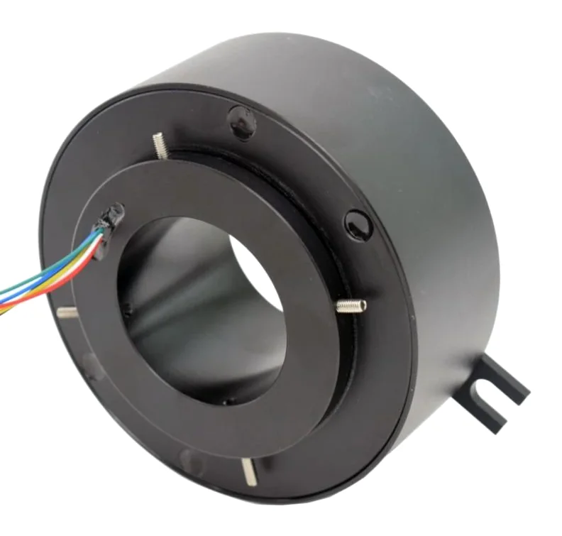
In short:Fast Ethernet (100BASE-TX, which EtherCAT and most PROFINET use) needs two pairs and is routinely carried through good contact slip rings; Gigabit (1000BASE-T) needs all four pairs and tighter impedance and crosstalk control. Specify the protocol, the cable run either side and the test method, and consider contactless or fibre links where speed, life or bandwidth rule out contacts.
Moving a camera, a remote I/O block or a servo drive onto a rotating table used to mean a stack of signal rings and a handful of analogue channels. Today the rotating side usually wants an Ethernet port. That is entirely achievable, but Ethernet is a high-frequency differential signal, not a DC circuit, and a slip ring that is fine for 24 V I/O can quietly corrupt frames. This guide covers what changes when data has to cross a rotating interface, how to specify and test it, and when to stop using contacts altogether.
100BASE-TX vs 1000BASE-T: how many pairs and why it matters
The first question is which physical layer the link will actually negotiate, because it sets the number of rings and the difficulty.
| 100BASE-TX (Fast Ethernet) | 1000BASE-T (Gigabit) | |
|---|---|---|
| Pairs carrying data | 2 (one transmit, one receive) | All 4, each carrying traffic in both directions |
| Rings needed for data | 4 | 8 |
| Signalling | MLT-3, 125 Mbaud | PAM-5, 125 Mbaud per pair, 250 Mbit/s per pair |
| Nominal impedance | 100 ohm differential | 100 ohm differential |
| Cabling reference | Cat 5 / Cat 5e | Cat 5e minimum for new installations |
| Sensitivity to crosstalk | Moderate | High: every pair transmits and receives at once, relying on echo and crosstalk cancellation in the PHY |
Most industrial Ethernet protocols run on 100BASE-TX. Texas Instruments’ industrial PHY guidance notes that while 10BASE-T, 100BASE-TX and 1000BASE-T are all used, most current protocols use 100BASE-TX, full duplex on two twisted pairs. EtherCAT’s physical layer is 100BASE-TX over standard Cat 5 industrial patch cable, with up to 100 m between devices (Beckhoff). Standard PROFINET copper is 100 Mbit/s full duplex, usually on the green four-wire (two-pair) shielded cable, with eight-core cable for Gigabit and a 100 m segment limit (PI North America).
The practical consequence: if every device on the rotating side is a fieldbus node, a two-pair, 100 Mbit/s ring is the right specification. Gigabit is worth paying for only when a device such as a machine-vision camera or an embedded PC genuinely needs it. Do not leave the link to auto-negotiate across a ring rated only for 100 Mbit/s; if both ends support Gigabit they will try to use it, and you will see link flapping or errors. Fix the speed in the switch configuration or buy the Gigabit ring.
What a slip ring does to an Ethernet channel
Ethernet standards define the whole channel, from PHY to PHY, as a set of loss and noise limits. A slip ring is an extra component inside that channel, and it affects all of the parameters that the cable and connectors do. Moog lists the three that matter most as insertion loss, return loss and crosstalk, which together set the signal-to-noise ratio and ultimately the bit error rate (Moog).
Impedance
Twisted-pair Ethernet is designed around 100 ohm nominal differential impedance (Dorsey, Machine Design). Each pair has to remain a 100 ohm transmission line as it leaves the cable, passes through the brush block and rings, and goes back into cable. Any section with different geometry, such as untwisted lead wires, a wide gap between the two rings of a pair, or a long stub to the brush, is an impedance discontinuity. It reflects part of the signal back towards the transmitter, which is measured as return loss. Ethernet-rated rings keep the two conductors of a pair on adjacent rings, keep internal wiring twisted as close to the termination as possible, and control ring spacing.
Crosstalk
Crosstalk is coupling from one pair into another, measured at the transmitting end (NEXT) and at the far end (FEXT). It matters most for Gigabit, because all four pairs transmit and receive simultaneously. The 1000BASE-T PHY cancels much of its own near-end crosstalk, but FEXT cancels less effectively, and the slip ring adds coupling that the PHY was not designed for (Dorsey). Rings for different pairs need physical separation or shielding between them, and Ethernet rings should be kept away from power rings carrying PWM motor current. If your slip ring also carries servo motor power, say so at enquiry stage; the layout of the ring stack and the grounding of shields matter.
Insertion loss
Insertion loss (attenuation) is the signal lost through the component. It is rarely the limiting factor for a single slip ring in a short machine-scale link, but it adds to the cable’s loss. A 90 m cable plus slip ring can fail where a 20 m cable plus the same ring passes comfortably.
Contact noise
The concern most engineers start with, the sliding contact itself, is usually the smallest problem in a well-designed ring. Dorsey estimates that a contact resistance of around 20 milliohms produces under 0.2 mV of noise, roughly -74 dB relative to the signal, which is insignificant against the PHY’s tolerance. Precious-metal contacts (gold-on-gold or fibre brush) keep resistance and its variation low. The contact becomes a problem when it wears, gets contaminated or bounces, which is why speed, life and environment still need to be specified.
Choosing contacts, speed and life for data rings
Data rings fail by the same mechanisms as signal rings, but the symptom is a link drop or error count instead of a noisy analogue value.
- Contact materials. Gold-on-gold or multi-filament fibre brushes are the norm for Ethernet. Carbon brushes are for power, not data.
- Speed. Many catalogue Ethernet rings are rated in the hundreds of rpm. For example, Servotecnica’s SVTS A Ethernet capsules and SVTS C Ethernet through-bore rings are listed at 500 rpm with 100BASE-T or 1000BASE-T options, and Moog’s AC7296 combines Gigabit Ethernet with 10 A and 25 A power rings in a one-inch bore, also at 500 rpm. If your shaft turns faster, look at high-speed slip rings or a contactless link.
- Life. Catalogue life figures vary widely by design; the Servotecnica catalogue, for instance, quotes 10 million revolutions for its capsule Ethernet range and 100 million for the through-bore range. Calculate your revolutions per year (rpm x hours x 60) and compare. Data rings tend to show wear-related errors before a power ring would show any measurable fault.
- Sealing. Contamination on a data ring causes intermittent errors that are hard to diagnose. Specify the IP rating for the real environment, not the cabinet.
For the full set of electrical and mechanical inputs, see how to specify a slip ring.
How Ethernet slip rings are tested
Ask any supplier how the Ethernet performance was verified. Moog’s approach, described in Dorsey’s article, evaluates the ring against the TIA/EIA-568 Cat 5e limits, which sit closest to the IEEE 802.3 requirements, and offers three methods:
- Full channel test. The ring is tested with a full 100 m of cable on a Gigabit tester with a pass/fail result. This is the most conservative and restricts ring size and layout.
- Partial cable, normalised. If your installation uses 20 m of cable, the ring is tested with 20 m and allowed the loss and noise equivalent of the remaining 80 m.
- Loss and noise budget. The system’s total loss and noise is calculated and compared with the 802.3 limits or with the specific transmitter and receiver in use. This is the most flexible.
Method 2 suits most machine builders because the cable length on each side of the ring is known. It also means you must tell the supplier what that length is.
Bench parameters are necessary but not sufficient. Before signing off a design:
- Run sustained traffic at the real protocol and cycle time while the ring rotates at maximum speed, in both directions, including starts and stops.
- Log the PHY or switch error counters (CRC errors, link-down events). For EtherCAT, monitor the lost-frame and working-counter errors at the master; for PROFINET, watch for cycle losses and alarms.
- Repeat at temperature extremes and after a run-in period.
A ring that passes a cable certifier but drops a frame every few thousand revolutions will cause nuisance trips on a cyclic fieldbus, so the rotating traffic test is the one that matters most.
Worked example: rotary indexing table with EtherCAT I/O
A packaging machine has a rotating table carrying an EtherCAT I/O coupler, two small servo drives and a 24 V supply. The table turns continuously at 30 rpm for 16 hours a day, 250 days a year. The EtherCAT master is in the main cabinet, 12 m of cable from the slip ring; the rotating side has 2 m to the coupler.
Data. EtherCAT is 100BASE-TX, so the ring needs one 100 Mbit/s Ethernet channel: four data rings. The rotating devices are in a line topology, so a single port is enough. No Gigabit device is present, so Gigabit is not specified.
Power. Servo motor power is carried separately through power rings sized for the drive’s input current, with the Ethernet rings physically separated from them and the cable shields terminated as the supplier recommends.
Speed and life. 30 rpm x 60 x 16 x 250 = 7.2 million revolutions a year. A ring rated for 10 million revolutions would need contact service in under 18 months; one rated for 100 million gives more than 13 years before the rated life is reached. That difference usually decides between a capsule and a larger through-bore design.
Test method. Ask for the partial-cable method with a 14 m total cable length, plus a rotating EtherCAT traffic test at the machine’s cycle time with the lost-frame counter logged.
What goes on the enquiry: protocol (EtherCAT, 100BASE-TX), one Ethernet channel, cable lengths 12 m and 2 m, connector preference (M12 D-coded or RJ45), continuous 30 rpm, 7.2 million revolutions a year, power ring currents and voltages, environment and IP rating.
Alternatives when contacts are the wrong answer
Contact slip rings are cost-effective and handle power as well as data, but they are not always the best data path.
- Capacitive or RF contactless data links. These couple the signal across a small air gap with no wear on the data path. Moog’s ROTOCAP range, for example, is listed for protocols including PROFINET, EtherCAT and Gigabit Ethernet in large through-bore formats. They are common on large-diameter tables where a contact ring would be bulky.
- Optoelectronic rotary data transmitters. Optical links such as Moog’s ROTORAY OE1 carry Fast or Gigabit Ethernet across rotation without contact but typically have no through-bore.
- Fibre optic rotary joints (FORJ). If the system can use fibre, a fibre optic rotary joint carries very high bandwidth with immunity to electrical noise. Media converters at each end turn it back into copper Ethernet. Hybrid units combine a FORJ with electrical rings for power.
- Wireless. Industrial Wi-Fi or other radio links avoid the rotating interface entirely for non-critical data, but latency and determinism are rarely good enough for cyclic motion fieldbuses, and the radio environment inside a steel machine is unpredictable. Treat wireless as suitable for diagnostics and video, not for closing a control loop.
For an overview of the product types, see Ethernet slip rings.
Common mistakes
- Specifying “Ethernet” without the speed, so a 100 Mbit/s ring is fitted on a link that negotiates Gigabit.
- Using ordinary signal rings for Ethernet because the circuit count was available.
- Not telling the supplier the cable lengths either side of the ring, so the channel budget cannot be checked.
- Mixing Ethernet rings next to PWM motor power rings without separation or shielding.
- Signing off on a static cable test without a rotating traffic test at the real protocol and cycle time.
- Ignoring life: a data ring that meets electrical limits on day one can generate errors as contacts wear.
Checklist
- Protocol and physical layer (EtherCAT, PROFINET RT or IRT, EtherNet/IP, Modbus TCP, plain TCP/IP; 100BASE-TX or 1000BASE-T)
- Number of independent Ethernet channels and topology on the rotating side
- Cable lengths on the stationary and rotating sides, and cable category
- Connector or termination style (RJ45, M12 D-coded or X-coded, flying leads)
- Maximum and continuous speed, direction, start/stop frequency
- Required life in revolutions and service interval you can accept
- Power and other signal circuits sharing the ring, with currents, voltages and whether any are PWM motor feeds
- Shield and earthing arrangement
- Environment: temperature, IP rating, washdown, vibration
- Test method requested (full channel, partial normalised, or budget) and rotating traffic test with error logging
- Whether a contactless or fibre data path would be acceptable
When you are ready, the spec builder collects these inputs in one place for our specialist engineering and supply partners to review.
Frequently asked questions
Can a standard slip ring carry Ethernet?
Sometimes at 10 or 100 Mbit/s over short cable runs, but it is a gamble. Ethernet is a 100 ohm differential signal, and ordinary signal rings are not laid out to hold that impedance or to keep pairs apart. An Ethernet-rated slip ring routes each pair on dedicated, matched rings with controlled spacing and shielding, and it is tested against the Ethernet channel limits. For anything going into production, specify an Ethernet-rated ring.
Is EtherCAT harder to pass through a slip ring than standard Ethernet?
Electrically it is the same 100BASE-TX physical layer, so a ring that passes Fast Ethernet cleanly will pass EtherCAT. The difference is tolerance to errors. EtherCAT and PROFINET IRT are cyclic, so a corrupted frame shows up as a lost cycle or a watchdog fault rather than a quiet retransmission. Ask for testing with your protocol and cycle time, and log error counters during a rotation test.
Do I need a Gigabit slip ring for PROFINET?
Not usually. Standard PROFINET runs at 100 Mbit/s full duplex over two pairs, so a 100BASE-TX rated ring is sufficient. Choose Gigabit only if a switch, camera or controller on the rotating side actually negotiates 1000BASE-T, or if you want headroom for a later upgrade. Gigabit uses all four pairs, so it needs eight data rings instead of four.
How is an Ethernet slip ring tested?
Good practice is to treat the slip ring as part of a cabling channel and test it against the Cat 5e limits used for IEEE 802.3: insertion loss, return loss, near-end and far-end crosstalk. That can be done with the full cable length plus the ring, a shorter cable with the ring given the balance of the 100 m budget, or a calculated loss and noise budget. Then run a traffic test while rotating.
When should I use a contactless rotary joint instead?
Consider capacitive, optical or fibre-optic transmission when the shaft speed is high, the required life is many hundreds of millions of revolutions, the environment is dirty or wet, or the bandwidth is beyond what a contact ring can carry. Contactless data links have no wear on the data path, but they are more expensive and you still need contacts or another method for power.
Sources
- How to choose slip rings for gigabit-Ethernet connectivity (Glenn Dorsey, Moog, Machine Design)
- Ethernet and high definition slip rings (Moog)
- Industrial Ethernet PHY requirements for EtherCAT and PROFINET (Texas Instruments SLAAEM2)
- EtherCAT highlights: physical layer (Beckhoff Information System)
- Can PROFINET projects employ Cat 5, 5e, Cat 6, 6a or Cat 7 cables? (PI North America)
- Slip rings catalogue v6.5 (Servotecnica)
Figures are summarised from the sources above and from manufacturers' published data on the date shown. Always confirm against the current datasheet for your exact part.