
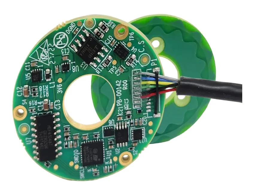
In short:Use an absolute encoder when the machine must know its position at power-up without moving, which is most servo axes, robot joints and anything that cannot safely home. Use an incremental encoder when a homing move at start-up is acceptable and you want the simplest, cheapest, fastest feedback, typically A/B/Z quadrature on RS-422.
Absolute vs incremental: the core difference
An incremental encoder tells the controller how far it has moved. It outputs two square waves 90° apart (A and B, so the controller can see direction) and usually an index pulse (Z) once per revolution or at a reference mark. The controller counts edges from a known point. Switch off, push the axis by hand, and that count is meaningless until the axis homes again.
An absolute encoder tells the controller where it is. Each position has a unique code read from the scale, so the true position is available the instant power returns, with no movement. Position is sent as a digital word over a serial interface.
The practical question is not which is “better”, but whether your machine can afford to move to find home every time it powers up, and what happens if it cannot.
Single-turn vs multi-turn absolute encoders
A single-turn absolute encoder measures one revolution and then repeats: 361° reads as 1° (POSITAL). That is enough for anything that turns less than one revolution over its full travel: a robot joint output, a rotary table measured at the table, a valve or a pan-tilt head.
A multi-turn encoder also counts complete revolutions. You need one whenever the encoder shaft turns many times over the axis travel: a motor driving a ball screw, a belt or rack, or a motor-side encoder before a gearbox. Counting revolutions with the power off is the hard part, and there are three ways to do it:
| Method | How it counts turns with power off | Strengths | Watch for |
|---|---|---|---|
| Gear train | Small gears drive additional code discs, one per stage | No battery; position retained indefinitely | Size, cost, and vulnerability to shock and vibration (POSITAL) |
| Battery-backed counter | A battery powers a low-power counter while main power is off | Compact; common on servo motors | Battery life, replacement schedule, and loss of the count (re-homing) if the battery runs flat while unpowered |
| Wiegand energy harvesting | A Wiegand wire produces a sharp voltage pulse as a magnet passes, even at near-zero speed, powering the counter | No battery or gears; maintenance-free | Check the supplier’s minimum turns and speed behaviour for your application |
POSITAL has used Wiegand-based counting since 2005, and battery-free multi-turn options are now common on servo motor encoders as well. If you choose a battery-backed design, write the battery check into the maintenance schedule and decide what the machine does if it powers up with the count lost.
A useful alternative in robot joints is to avoid multi-turn on the motor altogether. An absolute encoder on the gear output turns less than once over the joint’s range, so it gives absolute joint position with no battery, while a simpler motor-side encoder handles commutation and the speed loop (Allient). See our frameless motor sizing guide for that arrangement.
Encoder interfaces: A/B/Z, BiSS C, SSI, EnDat and others
Incremental (A/B/Z): usually RS-422 differential line driver signals, sometimes TTL, HTL (10–30 V) for PLC inputs, or analogue sin/cos 1 Vpp for interpolation in the drive. Resolution is in pulses per revolution (PPR); counting every edge of both channels gives four times that in counts (CPR) (RLS). Check the output frequency: a 5,000 PPR encoder at 3,000 rpm produces 5,000 × 3,000 / 60 = 250 kHz per channel, which the drive input must accept.
Absolute serial interfaces (Motion Control Tips):
| Interface | Owner / status | Direction | Notes |
|---|---|---|---|
| SSI | Widely used, simple | Unidirectional | Clock up to about 1.5 MHz depending on cable length; no CRC in the basic form |
| BiSS C | Open protocol | Bidirectional | Clock up to 10 MHz, CRC, can read parameters and temperature; BiSS Safety variant up to SIL3 |
| EnDat 2.2 | Heidenhain, proprietary | Bidirectional | Diagnostics and memory access; SIL3-capable versions |
| HIPERFACE DSL | SICK, licensed since 2016 | Bidirectional | Two wires shared with the motor power cable (one-cable motor connection); SIL3-capable |
| Drive-specific (Fanuc, Mitsubishi, Panasonic, Siemens DRIVE-CLiQ, Yaskawa) | Drive makers | Bidirectional | Some third-party encoders, such as Renishaw RESOLUTE, offer these variants |
The rule is simple: start from what the drive accepts. A brilliant encoder on an interface the drive cannot read needs a converter, adds latency and complicates safety certification.
Resolution vs accuracy vs repeatability
These three are routinely confused, and the confusion costs money:
- Resolution is the smallest step the encoder reports. For absolute rotary encoders, steps per revolution = 2ⁿ for n bits, so 13 bits is 8,192 steps (RLS).
- Accuracy is the maximum difference between reported and true position, including scale errors, readhead errors and mounting errors. RLS is explicit that higher resolution does not automatically mean higher accuracy.
- Repeatability is how closely the encoder returns the same reading at the same position. RLS’s rule of thumb is that it is typically 5 to 10 times better than accuracy.
For a control loop, resolution matters because it sets velocity-signal noise at low speed. For positioning, accuracy and repeatability matter. A 20-bit encoder reports about a million steps per turn, but that says nothing about whether those steps are in the right place.
Eccentricity: the installation error that dominates ring encoders
For a ring or disc encoder mounted off-centre by e on scale radius r, the peak angular error is roughly e / r radians. A 10 µm mounting error on a 25 mm radius ring gives 10 / 25,000 = 4 × 10⁻⁴ rad, about 83 arcsec, regardless of the encoder’s resolution. Ways to deal with it:
- Specify the shaft and hub run-out the ring needs, and check it on assembly.
- Use a larger diameter ring, since the error falls with radius.
- Use two readheads 180° apart. Renishaw states this cancels odd error harmonics including eccentricity, and quotes better than ±1 arcsec installed for its dual-readhead system (Fierce Electronics).
- Use an encoder with self-calibration or a calibration routine after installation.
Homing incremental axes
An incremental axis needs a homing sequence at start-up. Common methods:
- Home switch plus index pulse: move to a switch, then on to the next encoder index for a repeatable zero. The most common approach.
- Hard stop with torque or current limit: cheap, but repeatability depends on mechanics, and it loads the hardware every start.
- Reference marks on a linear scale: a single mark may need long travel to find. Distance-coded marks are spaced so the controller knows its absolute position after crossing two of them; Heidenhain quotes a maximum of 20 mm travel on its LS and LIP 500 scales and 80 mm on LB (HEIDENHAIN).
Homing is a safety question as much as a time question. If the axis carries a tool inside a fixture, a vertical load, or a robot arm among people, an unplanned homing move can be dangerous. That is often what pushes the specification to absolute.
Decision table
| Situation | Recommended | Why |
|---|---|---|
| Axis must not move at power-up (vertical, clamped, near people) | Absolute, multi-turn if the shaft turns more than once | Known position with no homing move |
| Robot joint | Absolute on output (single-turn), plus motor-side encoder | Battery-free absolute joint angle; sees wind-up |
| Servo motor on a ball screw or belt, frequent restarts | Multi-turn absolute, preferably battery-free | No homing, no battery maintenance |
| Conveyor, spindle, fan or speed-only loop | Incremental | Position at power-up irrelevant; simplest and cheapest |
| Simple stepper or PLC axis with a home switch | Incremental (A/B/Z, HTL or RS-422) | Homing is acceptable; wide PLC support |
| Long linear axis on a linear motor | Absolute linear scale, or incremental with distance-coded marks | Avoids long homing travel |
| High-accuracy rotary table | Absolute ring, dual readheads if eccentricity is significant | Accuracy limited by installation, not resolution |
| Harsh, dirty or wet environment | Magnetic, inductive or capacitive absolute | More tolerant of contamination than open optical |
Worked example: a vertical pick-and-place axis
Axis: vertical Z axis on a ball screw, 10 mm lead, 400 mm stroke, servo motor with brake. The gripper works inside a fixture, so moving blind at power-up could crash it. Required positioning accuracy at the gripper ±20 µm. Restarts happen several times a shift.
Turns over the stroke: 400 / 10 = 40 revolutions. A single-turn absolute encoder would not know which of the 40 turns it was on, so the choice is multi-turn absolute or incremental with homing.
Is homing acceptable? No. Homing upward from inside a fixture risks the gripper catching the part, and homing time at every restart costs throughput. Multi-turn absolute it is. A 12-bit turns counter (4,096 turns) covers the 40-turn stroke with room to spare.
Resolution check: even a 17-bit single-turn resolution gives 10 mm / 131,072 ≈ 0.08 µm per count at the load. A 2,500-line incremental encoder (10,000 CPR) would give 1 µm. Resolution is not the limiting factor; the ball screw’s lead accuracy and thermal growth are. Spend the money on the screw grade, not extra bits.
Battery or not: a battery-backed counter would work, but adds a maintenance item and a re-homing risk if a machine sits unpowered for a long period. A battery-free multi-turn (Wiegand or geared) is the cleaner choice for an OEM machine shipped to many sites.
Interface: match the drive. If the drive accepts BiSS C, a BiSS C multi-turn encoder or a servo motor with a battery-free multi-turn absolute encoder fitted as standard.
Result: servo motor with a battery-free multi-turn absolute encoder on BiSS C or the drive’s native protocol, and a power-off brake. Servo motors with this option include the Leadshine ELM2 range; for integrated stepper axes, the Novanta Liberty MDrive offers absolute options.
Example encoder families
- Absolute optical rings and scales: Renishaw RESOLUTE, with BiSS C and drive-specific protocols.
- Incremental optical: Renishaw TONiC and VIONiC for high-resolution linear and rotary axes.
- Absolute magnetic, through-bore: Renishaw RLS AksIM-4.
- Absolute inductive, sealed: Novanta Mini Ultra IncOder and Midi Ultra IncOder.
- Absolute capacitive, ultra-thin: Netzer VLX.
- Magnetic heads and tapes: Bogen AKS16 (absolute, multi-turn variant) and IKS11 (incremental).
Checklist
Send these to our engineers, or enter them in the spec builder:
- Rotary or linear; shaft, hollow shaft, ring or kit; available diameter and bore
- Total travel in revolutions or millimetres
- Whether the axis may move at power-up, and whether a homing sequence is acceptable
- Required accuracy and repeatability at the load, not just resolution
- Maximum speed (rpm or m/s) and the drive’s input frequency or clock limits
- Interface the drive or controller supports (A/B/Z RS-422, HTL, sin/cos, BiSS C, SSI, EnDat, HIPERFACE DSL, drive-specific)
- Battery acceptable or not for multi-turn
- Functional safety requirement (SIL or PL level)
- Environment: temperature, contamination (oil, dust, water), shock and vibration, IP rating
- Mounting tolerances achievable: run-out, ride height, alignment
- Cable length to the drive
See also our encoders overview.
Frequently asked questions
What is the difference between an absolute and an incremental encoder?
An incremental encoder outputs pulses as it moves, and the controller counts them from a reference point, so position is lost when power is removed and the axis must home again. An absolute encoder reads a unique code for every position, so it reports the true position immediately at power-up without any movement. Absolute encoders usually use a serial interface; incremental ones use A/B quadrature signals.
What is a multi-turn absolute encoder?
A single-turn absolute encoder knows its angle within one revolution but repeats after 360 degrees. A multi-turn encoder also counts complete revolutions, so a motor driving a ball screw or a belt knows its position over the whole stroke. Revolutions are counted using a gear train, a battery-backed counter, or an energy-harvesting Wiegand sensor that powers the counter from the shaft's own rotation.
Do multi-turn encoders need a battery?
Not always. Battery-backed designs keep a revolution counter alive while the main power is off, and need the battery checked and replaced. Geared multi-turn encoders count mechanically and need no battery but are larger and less tolerant of shock. Wiegand energy-harvesting encoders generate a pulse from shaft rotation to power the counter, so they need neither battery nor gears.
Is resolution the same as accuracy?
No. Resolution is the smallest step the encoder reports. Accuracy is how close the reported position is to the true position, and it is limited by the scale, the readhead and especially installation errors such as eccentricity. A 20-bit encoder reports about a million steps per turn but can still be several arcminutes out if the ring is mounted off-centre. RLS notes that higher resolution does not automatically mean higher accuracy.
Which absolute encoder interface should I choose?
Choose the interface your drive supports first. BiSS C is an open bidirectional protocol widely supported by servo drives. SSI is simple and unidirectional. EnDat 2.2 is Heidenhain's bidirectional protocol, and HIPERFACE DSL from SICK runs over two wires inside the motor cable. Drive makers such as Fanuc, Siemens, Mitsubishi and Yaskawa also have their own protocols, which some third-party encoders support.
How do incremental encoders home?
The axis moves to a home switch, a hard stop or a reference mark on the scale, and the controller sets zero there; often it combines a switch with the next index pulse for repeatability. Distance-coded reference marks reduce homing travel: Heidenhain's coded linear scales establish the absolute reference after crossing two successive marks, within 20 mm on its LS and LIP 500 scales.
Sources
- POSITAL: Singleturn and multiturn encoders
- RLS encoder handbook: Resolution, accuracy and repeatability
- Motion Control Tips: Absolute encoder interfaces, SSI, BiSS, HIPERFACE, EnDat
- HEIDENHAIN: Distance-coded reference marks
- Fierce Electronics: Dual-readhead rotary encoder from Renishaw
- Allient: How to select a motor for a robot joint
Figures are summarised from the sources above and from manufacturers' published data on the date shown. Always confirm against the current datasheet for your exact part.