
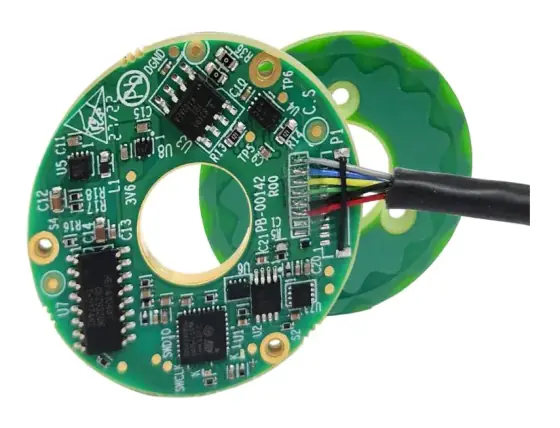
In short:Match the encoder interface to what the drive accepts first, then to cable length and data needs. A/B/Z on RS-422 is the universal incremental choice to about 100 m; 1 Vpp sin/cos gives high interpolated resolution; BiSS-C, SSI and EnDat 2.2 carry absolute position digitally; and one-cable interfaces such as HIPERFACE DSL run inside the motor cable.
Which encoder interface to use: the short answer
The encoder interface is the electrical and protocol link between the encoder and the drive or controller. Choose it in this order:
- What the drive accepts. A perfect encoder on an unsupported protocol is useless. Read the drive’s feedback input list first.
- Incremental or absolute. Incremental signals (A/B/Z, sin/cos) need homing; serial absolute protocols report position at power-up. See absolute vs incremental encoders for that decision.
- Cable length and environment. Long runs, drag chains and noisy cabinets push you towards differential signals, higher supply voltages or protocols with line-delay compensation.
- Data needs. Diagnostics, temperature, electronic nameplates and functional safety need a bidirectional protocol.
- Cable count. If the machine cannot take a second cable through a drag chain or slip ring, a one-cable protocol is worth the restriction on motor choice.
Encoder interface comparison table
| Interface | Signal type | Position | Typical max cable (HEIDENHAIN) | Bidirectional | Notes |
|---|---|---|---|---|---|
| TTL / RS-422 A/B/Z | Differential square waves, 5 V | Incremental | 100 m | No | Universal servo and motion controller input |
| HTL A/B/Z | Push-pull square waves, 10–30 V | Incremental | up to 300 m (frequency dependent) | No | PLC counters, long runs, heavy industry |
| 1 Vpp sin/cos | Differential analogue, 1 V peak-to-peak | Incremental (absolute via EnDat01 or similar) | 150 m | No | Interpolated to high resolution in the drive |
| SSI | Clocked serial, RS-422 | Absolute | 100 m | No | Simple, slow clock, widely supported |
| BiSS-C | Clocked serial, RS-422 | Absolute | BiSS Association states up to 1,000 m | Yes | Open protocol, CRC, line-delay compensation |
| EnDat 2.2 | Clocked serial, RS-485 | Absolute | 100 m | Yes | HEIDENHAIN protocol; diagnostics and additional data |
| HIPERFACE DSL | Serial on two wires, RS-485 | Absolute | 100 m (TI reference design) | Yes | One-cable, power and data on one pair |
| Tamagawa T-format / Nikon A-format | Half-duplex serial, RS-485, 2.5 Mbit/s | Absolute | Drive-maker dependent | Request/response | Common on Asian servo motors |
| Fanuc, Mitsubishi, Panasonic, Yaskawa serial | Proprietary | Absolute | 30 m (50 m on some Fanuc/Panasonic) | Yes | Locked to that drive family |
Cable figures are from the HEIDENHAIN interfaces brochure unless stated; BiSS from the BiSS Association; HIPERFACE DSL from Texas Instruments TIDUA76; Tamagawa and Nikon from Analog Devices AN-2619 and AN-2635. Other makers’ encoders and cables can differ; treat these as planning values.
Incremental A/B/Z: TTL, HTL and RS-422
An incremental encoder outputs two square waves, A and B, 90° apart so the receiver can tell direction, plus an index pulse Z once per revolution. Counting every edge of both channels (×4 decoding) gives four counts per line: a 2,500-line encoder gives 10,000 counts per revolution.
The names for the electrical options are used loosely, so be precise in a specification:
- Open collector sinks current only and needs a pull-up. Dynapar describes it as suited to short runs, typically under about 30 ft (9 m) (Dynapar).
- TTL / RS-422 line driver outputs A, /A, B, /B, Z, /Z as differential pairs at 5 V. The receiver looks at the difference between each pair, so noise picked up equally on both wires cancels. HEIDENHAIN allows up to 100 m for its TTL encoders (HEIDENHAIN).
- HTL (high threshold logic) is push-pull at the supply voltage, typically 10 to 30 V. The bigger swing gives a large noise margin, which is why it is common on PLC counter cards and in steel, paper and crane drives. HEIDENHAIN lists up to 300 m for HTL, depending on output frequency, supply and temperature; single-ended HTL only 100 m.
Frequency and edge separation
The real limit on an incremental link is often frequency, not cable length. Output frequency is lines × rev/s: a 5,000-line encoder at 6,000 rpm outputs 500 kHz, and with ×4 decoding the receiver must resolve edges 0.5 µs apart. HEIDENHAIN’s rule is that cable reduces the minimum edge separation by about 0.2 ns per metre, and the receiving electronics should be designed for 90% of the resulting value to leave a 10% margin. Check the drive’s maximum input frequency (usually quoted after ×4) against the motor’s top speed.
Sin/cos 1 Vpp: high resolution by interpolation
A sin/cos encoder outputs analogue sine and cosine signals instead of square waves, nominally 1 V peak-to-peak (HEIDENHAIN allows 0.6 to 1.2 Vpp). The drive digitises both and computes the angle within each signal period by arctangent, so a scale with 2,048 periods per revolution can be interpolated many times over. Design World notes the signals “allow high levels of interpolation, for better resolution” but are “more prone to noise than digital signals”, which is why they are always transmitted differentially (Design World).
HEIDENHAIN allows 150 m for 1 Vpp and specifies its parameters up to 20% of the −3 dB cutoff frequency; the drive should monitor amplitude and flag a fault outside roughly 0.30 to 1.35 Vpp (HEIDENHAIN). Interpolated resolution is only as good as the signal: contamination, misalignment and noise show up as interpolation error at the signal period, which a servo loop will see as velocity ripple.
SSI, BiSS-C and EnDat 2.2: clocked serial absolute
Clocked serial interfaces send a position word on request. The controller sends a clock on one RS-422/485 pair and the encoder returns data bits on another, so four signal wires plus power.
SSI (synchronous serial interface) is the simplest. It is unidirectional: the encoder sends position and nothing else. HEIDENHAIN’s SSI encoders use 13-bit single-turn or 25-bit multi-turn words, a clock period of 1 to 10 µs (100 kHz to 1 MHz) and up to 100 m of cable. Some SSI encoders also carry 1 Vpp, TTL or HTL incremental tracks alongside.
BiSS-C keeps SSI-compatible hardware but adds bidirectional register communication, a CRC and automatic line-delay compensation. iC-Haus introduced BiSS in 2002; the protocol is published openly and the BiSS Association grants free licences. The Association quotes clock rates up to 10 MHz on RS-422 and cable lengths up to 1,000 m, and notes that BiSS devices can be switched to SSI mode for controllers without a BiSS input (BiSS Association).
EnDat 2.2 is HEIDENHAIN’s bidirectional protocol. The clock runs from 100 kHz to 2 MHz depending on cable length, or up to 8 or 16 MHz with propagation-time compensation in the drive. Beyond position it can transmit diagnostics, a second position value, temperature, commutation data, acceleration and timestamps. The EnDat22 ordering designation has no incremental signals; EnDat01 adds 1 Vpp tracks for older inputs (HEIDENHAIN).
Why line delay matters
At about 6 ns per metre, a 40 m cable adds roughly 480 ns of round-trip delay between the clock edge leaving the drive and the data bit arriving back. Without compensation, a practical rule of thumb is to keep the clock half-period longer than that delay, which caps a 40 m SSI link at around 1 MHz. BiSS-C and EnDat 2.2 measure and subtract the delay, so they can clock much faster on the same cable and return a full position word well inside a fast servo cycle.
Drive-maker serial: Tamagawa, Nikon and others
Many Japanese and Asian servo motors use half-duplex RS-485 protocols where the drive sends a request and the encoder replies on the same pair:
- Tamagawa T-format: 2.5 Mbit/s, four wires (+5 V, 0 V, DATA+, DATA−) in one shielded cable; the reply carries single-turn and multi-turn position, encoder ID, alarm bits and an 8-bit CRC (Analog Devices AN-2619).
- Nikon A-format: 2.5 Mbit/s half-duplex RS-485 with a 3-bit encoder address; the basic reply carries 20-bit single-turn and 16-bit multi-turn position with an 8-bit CRC (Analog Devices AN-2635).
- Fanuc, Mitsubishi, Panasonic, Yaskawa and Siemens DRIVE-CLiQ each have their own interfaces; third-party encoders exist for some. HEIDENHAIN lists 30 m cable limits for the first four (up to 50 m for some Fanuc and Panasonic) and 100 m at 24 V for DRIVE-CLiQ.
These are fine choices inside one drive family, but they lock the motor to that drive. If you might change drive supplier, prefer BiSS-C or EnDat.
One-cable vs two-cable feedback
A conventional servo has two cables: power and a separate feedback cable. One-cable technology puts the encoder link on a shielded twisted pair inside the motor power cable.
HIPERFACE DSL (specified and owned by SICK) is the best-known example. Texas Instruments’ reference design describes 9.375 MBaud on RS-485 over two wires that carry power and data together, half-duplex, up to 100 m, with a shortest feedback cycle of 12.1 µs. The pair needs 100 to 120 Ω impedance, and safe position transmission supports SIL2 or SIL3 to IEC 61508 (Texas Instruments). EnDat 3 from HEIDENHAIN runs at 12.5 Mbit/s for up to 100 m (25 Mbit/s up to 40 m) and can modulate data onto the supply pair for hybrid motor cables.
| Two-cable | One-cable | |
|---|---|---|
| Connectors and cable cost | Higher | Lower |
| Drag chain and slip ring space | Two cables or more channels | One cable; fewer slip ring circuits |
| Choice of motor, encoder, drive | Wide | Must all support the same protocol |
| Noise exposure | Feedback separated from power | Pair sits beside PWM power conductors; cable design is critical |
| Retrofit flexibility | Easy to swap encoder type | Limited |
Noise, shielding and supply voltage drop
Most encoder faults on commissioning are cabling, not encoders. The rules that prevent them:
- Differential signals over shielded twisted pairs. Dynapar calls shielded twisted-pair cable, preferably low-capacitance, “a must”, and differential signalling “paramount” for long runs or noisy plant (Dynapar).
- Terminate RS-422/485 lines with the drive’s specified termination (HEIDENHAIN’s input circuits use 120 Ω).
- Shield bonded 360° at the connectors, and feedback cables routed away from motor and brake cables.
- Check supply voltage drop on 5 V encoders. HEIDENHAIN gives ΔU = I × 2 × 1.05 × L / (56 × A), with L in metres and A in mm². A 150 mA encoder on 40 m of 0.14 mm² cores loses about 1.6 V, which takes a 5 V supply below most encoders’ minimum. On 0.5 mm² cores it loses 0.45 V. Use thicker supply cores, sense lines, or a 10–30 V encoder variant.
Worked example: gantry axis with a 40 m drag-chain run
Requirement: Long-travel gantry. Servo motor at up to 4,000 rpm, absolute position needed at power-up, 40 m from the motor to the drive through a drag chain. The drive accepts A/B/Z, 1 Vpp, SSI, BiSS-C and EnDat 2.2. Cycle time of the position loop 62.5 µs.
Options:
- A/B/Z RS-422, 2,500 lines: 10,000 counts per rev, 167 kHz at 4,000 rpm, comfortably inside 100 m. But it is incremental, so it fails the power-up requirement.
- SSI, 25-bit multi-turn: absolute, but with ~480 ns round-trip delay the clock is held to about 1 MHz. A 25-bit word takes 25 µs at 1 MHz, and HEIDENHAIN specifies a further 17–20 µs pause before the next read, so one read uses most of the 62.5 µs cycle, with no CRC.
- BiSS-C, 23-bit single-turn plus multi-turn: line-delay compensation allows a 10 MHz class clock, so the full word returns in a few microseconds, with CRC on every frame.
- Supply: 40 m of 0.14 mm² at 150 mA drops 1.6 V. Specify 0.5 mm² supply cores or a sense-line arrangement.
Choice: BiSS-C multi-turn encoder, drag-chain-rated shielded cable with 0.5 mm² supply cores, CRC errors mapped to a drive fault. If the motor supplier offered HIPERFACE DSL and the drive supported it, one-cable would remove the second cable from the drag chain altogether.
Products in our range to consider
These encoders are available through our supply network, with the interfaces stated in their published data:
- Bogen IKS23: rugged incremental magnetic head with RS-422 or HTL push-pull output and a 10–30 VDC supply option.
- Bogen IKS15: incremental magnetic head with analogue sin/cos 1 Vpp or 2 Vpp output.
- Bogen AKS16 / AKS16-MT: absolute magnetic head with BiSS-C, SSI, ABZ and other outputs, up to 20 bit.
- Netzer VLX: ultra-thin hollow-shaft capacitive absolute encoder with SSI or BiSS-C, up to 23 bit.
- Netzer VLA: hollow-shaft capacitive encoder with analogue sine/cosine output for large bores.
- Midi Ultra IncOder: inductive absolute encoder, 75–300 mm OD, with ASI, SSI, SPI, BiSS-C or A/B/Z interfaces.
- KappaSense FLEXe: capacitive linear encoder with BiSS-C or A quad B output, strokes up to 1.9 m.
For choosing the sensing technology, see magnetic vs capacitive vs optical encoders and how to select an encoder.
Checklist
Send these to our engineers, or enter them in the spec builder:
- Drive or controller make and model, and its supported feedback inputs
- Incremental or absolute; single-turn or multi-turn
- Resolution (lines, bits or µm) and required accuracy
- Maximum speed, to check output frequency or clock rate
- Cable length, route (drag chain, slip ring) and cable type
- Supply voltage available at the encoder end
- One-cable or two-cable preference
- Diagnostics, temperature or functional safety requirements
- Electrical environment: nearby drives, welders, VFDs
- Connector type and IP rating
For the wider family, see our encoders overview.
Frequently asked questions
What is the difference between TTL, HTL and RS-422 encoder outputs?
All three carry the same A/B/Z quadrature pulses at different voltage levels. TTL encoders run from 5 V, and in motion control 'TTL' usually means differential RS-422 line-driver outputs with complementary channels. HTL uses 10 to 30 V push-pull outputs, which suits PLC inputs and long runs; HEIDENHAIN lists up to 300 m for HTL against 100 m for TTL. Single-ended outputs are the most sensitive to noise.
Is BiSS-C better than SSI?
BiSS-C is hardware compatible with SSI but adds bidirectional register access for parameters and diagnostics, CRC error checking and automatic line-delay compensation, which allows faster clock rates on long cables. SSI is simpler, unidirectional and supported almost everywhere. If the drive supports BiSS-C, it is usually the better choice for a new design; many BiSS encoders can also be switched to SSI mode.
What is a one-cable encoder interface?
A one-cable interface carries encoder data, and usually encoder power, on a twisted pair inside the motor power cable, so there is no separate feedback cable. HIPERFACE DSL from SICK runs at 9.375 MBaud over two wires for up to 100 m, and HEIDENHAIN's EnDat 3 can also run on two wires in hybrid motor cables. The motor, cable and drive all have to support the same protocol.
How long can an encoder cable be?
It depends on the interface, clock rate and supply. HEIDENHAIN's limits are a useful guide: 1 Vpp 150 m, TTL 100 m, HTL up to 300 m, SSI 100 m, EnDat 2.2 100 m, and drive-maker serial interfaces from Fanuc, Mitsubishi, Panasonic and Yaskawa about 30 m. Check supply voltage drop as well as signal quality, because a 5 V encoder can fall below its minimum supply on a long thin cable.
Why use a sin/cos encoder instead of a digital one?
A 1 Vpp sine/cosine encoder outputs analogue signals that the drive can interpolate far beyond the number of signal periods, giving high resolution and smooth velocity at low speed from a modest scale. The trade-off is noise sensitivity: analogue signals need differential transmission, good shielding and a drive input designed for them. Many servo drives and CNC controls accept 1 Vpp directly.
Can I use a Tamagawa or Nikon protocol encoder with any drive?
Only if the drive supports that protocol. Tamagawa T-format and Nikon A-format are half-duplex RS-485 serial interfaces at 2.5 Mbit/s, widely used on Asian servo motors, and each has its own frame structure and CRC. Several drive and chip makers support them, but the protocol and baud rate must match exactly. Confirm the drive's encoder input list before choosing a motor or encoder.
Sources
- HEIDENHAIN: Interfaces of HEIDENHAIN encoders (brochure 1078628)
- BiSS Association: About BiSS
- Texas Instruments TIDUA76: HIPERFACE DSL encoder interface reference design
- Analog Devices AN-2619: Tamagawa absolute encoder protocol support
- Analog Devices AN-2635: Nikon A-format absolute encoder protocol support
- Dynapar: Encoder 101, selecting the right output (white paper)
- Design World: Differences between incremental and sine/cosine encoders
Figures are summarised from the sources above and from manufacturers' published data on the date shown. Always confirm against the current datasheet for your exact part.