
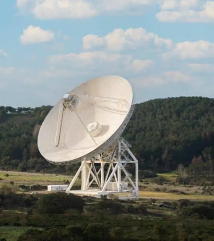
In short:Start from the beamwidth: a large dish at Ka-band leaves a pointing budget of only a few hundredths of a degree, and backlash, encoder error, structural deflection and wind all have to fit inside it. Then size the drives for wind torque, choose slip rings and RF rotary joints for continuous azimuth, and seal everything for years outdoors.
Typical requirements
| Pointing accuracy (ground positioners) | About 0.017–0.05° RMS standard; 0.003° high-accuracy options (published range) |
|---|---|
| Axis speed | 1–10 rpm for heavy az/el positioners; 50°/s typical, 200°/s max for LEO X-Y pedestals |
| Maritime VSAT motion | Roll ±20°, pitch ±10°, yaw ±8°; 0.2° peak mis-pointing (1.25 m Ku example) |
| Positioner payload and torque | 50–3,000 kg payload; 100–3,000 Nm per axis (one published az/el range) |
| RF rotary joints | Up to 67 GHz on positioner options; capsule RF slip rings to about 3 GHz |
| Wind | About 80–100 km/h operational, 200 km/h survival (published LEO/MEO tracking range) |
| Temperature | -40 to +70 °C outdoor ground equipment |
Where satcom motion is used
Antenna positioners point a dish or flat panel at a satellite and keep it there. The market splits three ways:
- Ground stations and teleports: fixed az/el or X-Y pedestals, from small LEO tracking terminals to dishes of several metres, tracking geostationary satellites slowly or LEO passes quickly.
- Maritime VSAT: stabilised radome terminals that hold pointing while the ship rolls, pitches and yaws.
- Satcom on the move (SOTM): vehicle and aircraft terminals that need fast, light, stabilised axes.
The motion components are similar across all three: brushless servo motors, low- or zero-backlash gearing or direct drive, absolute encoders, slip rings with RF rotary joints, and drives that close tight position loops outdoors.
Start with the pointing budget
The dish sets the accuracy you need. As a rule of thumb, a parabolic dish’s 3 dB beamwidth is about 70 × λ / D degrees, and pointing loss is about 12 × (error / beamwidth)² dB.
Worked example: 2.4 m dish at Ka-band receive
- At 20 GHz, λ = 15 mm. Beamwidth = 70 × 15 / 2,400 = 0.44°.
- To keep pointing loss under 0.25 dB: error = 0.44 × √(0.25 / 12) = 0.063°.
- That 0.06° is the whole budget. Split it between encoder accuracy, residual backlash, gear and structural wind-up, structural deflection under wind and gravity, thermal distortion, and the tracking error of the control loop.
- An encoder taking 10% of the budget must be accurate to about 0.006° (about 23 arcsec). A 16-bit encoder resolves 0.0055°; for accuracy as well as resolution, look at 19-bit and above.
The same dish at Ku-band (12 GHz) has a beamwidth near 0.73°, so the budget roughly doubles. Published ground positioners show what is achievable: MDL’s ASY-AE range quotes 0.017–0.05° RMS, with a 0.003° high-accuracy option, backlash-free drives and absolute encoders. The stabilised Intellian v130 maritime terminal (1.25 m, Ku-band) quotes 0.2° peak mis-pointing at maximum ship motion.
Az/el, X-Y and three-axis mounts
| Geometry | Strength | Weakness |
|---|---|---|
| Az/el | Simple, compact, ideal for GEO | “Keyhole” near zenith: azimuth must spin very fast for overhead passes |
| X-Y | No zenith keyhole, lower peak speeds for LEO | Taller, keyhole moves to the horizon |
| Three-axis (az/el plus cross-level or tilt) | Handles overhead passes and ship motion | More axes, more mass, more control complexity |
Comtech’s X-Y LEO/MEO pedestals quote 50°/s typical and up to 200°/s, 100°/s² acceleration and 0.05–0.10° pointing, and are designed to need no cable wrap, slip rings or rotary joints. Maritime terminals like the v130 use three-axis stabilisation (azimuth, elevation, cross-level) with unlimited azimuth, specified for roll ±20°, pitch ±10° and yaw ±8° at up to 12°/s and 5°/s².
Drives, gearing and backlash
Heavy positioners turn slowly with large torque. The ASY-AE range, for example, runs 1–10 rpm with 100–3,000 Nm per axis for payloads of 50–3,000 kg. The usual drivetrains:
- Slew ring with pinion, often with two motors biased against each other so one always holds the gear flank. Simple and strong; needs a bias strategy in the drive.
- Strain-wave or precision cycloidal reducers for zero or near-zero backlash in a compact axis. Hollow-shaft sets such as the Harmonic Drive SHG leave a bore for cables and waveguide. See harmonic vs planetary vs cycloidal and gearboxes.
- Direct drive with a large-bore frameless torque motor, such as the Akribis ADR-P (110–360 mm OD, bores to 229 mm). No backlash and very smooth tracking, but holding torque under wind needs careful sizing, often with a brake.
- Worm gears are self-locking and cheap, but backlash and wear limit them to coarse pointing.
Sizing for wind torque
Wind usually sets drive and brake torque on fixed antennas. Wind force rises with the square of speed: F = ½ ρ v² A C, where C is a force coefficient that depends on the dish shape and angle to the wind. Get the coefficients from the antenna maker. As an illustration, a 2.4 m dish (4.5 m²) at 72 km/h (20 m/s) with an assumed coefficient of 1.5 sees about 1.7 kN; if the centre of pressure sits 0.3 m from the elevation axis, that is about 500 Nm. At 200 km/h survival the same dish sees about 7.7 times the force, which is why many systems stow and brake rather than drive in storms. Check operational wind (full accuracy), drive-to-stow wind, and survival wind (stowed, brakes on) separately.
Encoders on antenna axes
Put an absolute encoder on the axis output so the controller sees the antenna angle, not the motor angle. Hollow, large-bore types let cables and RF pass through. Options include:
- Capacitive ring encoders such as the Netzer VLP, built for harsh environments and tested to MIL-STD-810, with bores to 171 mm and -40 to +105 °C.
- Optical absolute rings such as Renishaw RESOLUTE where arc-second accuracy matters and the axis can be kept clean and dry.
- Off-axis magnetic rings like the RLS AksIM-4 for robust mid-accuracy axes.
Compare technologies in absolute vs incremental encoders and browse encoders.
Slip rings and RF rotary joints
An unlimited azimuth axis needs a slip ring for power, motor and encoder signals and a modem or network link, plus an RF rotary joint for the RF path unless the RF electronics ride on the rotating side. MDL lists 12-channel slip rings as standard on its positioners, with RF rotary joints up to 67 GHz as options. At lower frequencies, RF capsule slip rings such as the Servotecnica SVTS A 06 pass coaxial signals up to 3 GHz alongside 24 signal circuits; through-bore rings such as the SVTS C carry Ethernet and power around a central rotary joint.
Specify each RF channel by frequency band, power, insertion loss, VSWR and wow (variation with rotation), and specify Ethernet through the ring end to end (Ethernet through slip rings). Our satellite antenna slip ring page and the fibre optic rotary joint type cover high-bandwidth options. For marine terminals see marine slip rings.
Environment and compliance
- Outdoor sealing: IP66 or better on drives, encoders and slip rings to IEC 60529; drains and breathers to stop condensation; UV-stable cables.
- Temperature: ground equipment is commonly rated -40 to +70 °C. Check grease, seals and brush slip ring performance at the cold end.
- Marine: IEC 60945 environmental tests and MIL-STD-167-1 vibration appear on maritime VSAT data sheets, alongside salt-mist corrosion protection.
- Defence and vehicle terminals: MIL-STD-810H environmental tests are common; see our defence and security section.
- Regulatory: pointing accuracy also matters legally. ETSI EN 302 340 (vessels) and EN 303 978 (mobile platforms, Ka-band) set antenna and off-axis emission requirements that depend on keeping the beam on target.
Typical pitfalls
- Ignoring the pointing budget and buying an encoder with good resolution but poor accuracy.
- Sizing drives for still air and finding the axis cannot hold position at operational wind.
- Specifying a slip ring without the RF channels, or an RF joint without wow and VSWR limits.
- Choosing az/el for LEO overhead passes without checking the keyhole velocity.
- Cold-weather seals and grease that stiffen at -30 °C and overload the drive.
Send us your dish, band, accuracy, wind and platform requirements and our specialist engineering and supply partners can propose drives, encoders and slip ring assemblies for each axis.
Standards to have in view
- IEC 60529 (IP codes)
- IEC 60945 (maritime navigation and radiocommunication equipment: general requirements and environmental tests)
- MIL-STD-167-1 (shipboard vibration)
- MIL-STD-810H (environmental engineering and laboratory tests)
- ETSI EN 302 340 (earth stations on board vessels, 11/12/14 GHz)
- ETSI EN 303 978 (earth stations on mobile platforms, Ka-band)
Which standards apply depends on the end product and its market. Your engineer will confirm what the component itself needs to meet.
Frequently asked questions
How accurate does an antenna positioner need to be?
Work it out from the beamwidth. A dish's 3 dB beamwidth is roughly 70 × wavelength ÷ diameter in degrees, and pointing loss is about 12 × (error ÷ beamwidth)² dB. A 2.4 m dish at 20 GHz has a beamwidth near 0.44°, so holding loss to 0.25 dB means about 0.06° total pointing error. Encoder, backlash, structure and wind deflection must all fit inside that budget.
Do antenna positioners need slip rings?
Only if an axis must rotate continuously. Maritime VSAT and many ground positioners have unlimited azimuth, which needs a slip ring for power and data and often an RF rotary joint for the signal path. Limited-travel axes, and X-Y pedestals designed to avoid cable wrap, can use a cable wrap or energy chain instead, which is simpler and avoids contact wear.
What is the keyhole problem on az/el mounts?
When a satellite passes close to the zenith, an az/el mount must swing its azimuth axis very fast to follow it, often faster than the drive allows. That creates a small blind cone overhead. LEO tracking systems avoid it with X-Y or three-axis mounts, which need much lower peak velocities for overhead passes.
How do I remove backlash from an antenna drive?
Common approaches are dual pinions driven against each other on a slew ring (torque bias or split-torque), preloaded or zero-backlash gearing such as strain-wave sets, or direct-drive torque motors with no gearing at all. Whichever you use, put a high-resolution absolute encoder on the axis output so the controller sees the real antenna angle.
What sealing does an outdoor antenna drive need?
Expect rain, UV, salt, ice and large daily temperature swings for many years. Ask for IP66 or better on drives and encoders, shaft seals rated for the temperature range, corrosion protection for marine sites, drain paths so condensation does not collect, and heaters or breathers where moisture is a risk. Brush slip rings should be sealed and rated for the low-temperature end.
What should I send for an antenna positioner enquiry?
Send antenna diameter and mass, band and beamwidth, axis geometry and travel, required velocity and acceleration, pointing accuracy budget, operational and survival wind speed, temperature range, platform (fixed, vessel or vehicle) and its motion, slip ring circuits plus RF channels and frequencies, encoder interface and any ETSI, IEC 60945 or MIL-STD requirements.
Sources
- MDL Technologies: ASY-AE az/el positioner datasheet
- Comtech: LEO/MEO X-Y tracking antenna systems datasheet
- Intellian: v130 maritime VSAT brochure
- Bob Atkins: Estimating gain loss due to pointing error
Figures are summarised from the sources above and from manufacturers' published data on the date shown. Always confirm against the current datasheet for your exact part.